Table of Contents
Advertisement
Quick Links
Advertisement
Table of Contents

Subscribe to Our Youtube Channel
Related Manuals for IAS Smartzone

Summary of Contents for IAS Smartzone
- Page 1 Smartzone TECHNICAL MANUAL www.ias.net.au...
- Page 2 Profile Smartzone Plus Control System. COPYRIGHT This publication is Copyright © 2005 Innovative Air Systems Pty Ltd (IAS). All rights reserved. No part of this publication may be reproduced, stored in any retrieval system or transmitted, in any form or by any means, electronic, mechanical, photocopying, recording or otherwise, without the prior written permission of Innovative Air Systems Pty Ltd.
-
Page 3: Table Of Contents
SMARTZONE TECHNICAL MANUAL CONTENTS CONTENTS INTRODUCTION ........4 SYSTEM OVERVIEW . - Page 4 4.2.2 1234/5678 Zone Expansion Module 4.2.3 LCD Touchpad 4.2.4 Room Controllers 4.2.5 Supply Air Sensor 4.2.6 Motorised Damper SMARTZONE SPILL SYSTEM OVERVIEW 4.3.1 Bypass Damper 4.3.2 Spill Zone METHODS FOR CALCULATING BYPASS/SPILL SETPOINT 4.4.1 Air Quantity 4.4.2 Supply Air Temperature 4.4.3 Diffuser Noise...
- Page 5 SMARTZONE TECHNICAL MANUAL CONTENTS LCD TOUCHPAD USER GUIDE ......21 TOUCHPAD AND DISPLAY LAYOUT SELECTING A ZONE...
-
Page 6: Introduction
(variable air volume) zoning system at lower capital and ongoing costs than traditional methods. The Smartzone system is designed for use with any HVAC system with a centralized cooling and/or heating source. Smartzone is not suitable for applications utilising individual zone reheat. -
Page 7: System Overview
2.1.1 Zone Temperature Management One of the strengths of the Smartzone is the way it handles each zone as an independent entity. There are three variables that influence the damper position for each zone. Two of these are measured (actual zone temp and supply air temp) and the third is set (setpoint or target temp). -
Page 8: Plant Control
As the thermal bank effect is depleted the return/bypass mix increases in temperature and the compressor cycles back on. � It is recommended that the Smartzone system remain on at all times when using this method. -
Page 9: Safety Modes
Smartzone when using the Bridge Module. 2.1.4 Safety Modes It is anticipated the Smartzone system will be widely used with reverse cycle (heat pump) air-conditioning units. The majority of these units utilise scroll, rotary or reciprocating compressors. Although some of these compressors can pump liquid or operate at excessive discharge pressures for periods of time it is not desirable. -
Page 10: System Components
SMARTZONE TECHNICAL MANUAL SYSTEM OVERVIEW SYSTEM COMPONENTS The Smartzone system is tailored to suit each application using some or all of the following components: Main Processor Module 1234 Expansion Module 5678 Expansion Module (required for 5...8 zone systems) LCD Touchpad... -
Page 11: Motorised Barrel Damper
2.2.9 Touchpad Expansion Module (Optional) The optional touchpad expansion module amplifies the communications signal to allow up to nine touchpads to be connected to the Smartzone system. Additional touchpad expansion modules may be added if more touchpads are required. 2.2.10 Bridge Module (Optional) The optional bridge module is an interface between the Smartzone communications protocol and that used by selected IAS HVAC plant controllers. -
Page 12: Technical Specifications
SMARTZONE TECHNICAL MANUAL TECHNICAL SPECIFICATION TECHNICAL SPECIFICATIONS ELECTRICAL REQUIREMENTS Power input to system ......24 Volts AC ± 10 % Line Frequency ........50 Hz SYSTEM POWER CONSUMPTION Number of Zones 4Nm Motor 4Nm with Clutch 11.2 VA 9.8 VA 16.4 VA 12.8 VA... -
Page 13: Sensor Inputs
4 x Yellow – 5678 Zone Expansion Module zone motor closed ZONE MOTOR RATINGS The Smartzone system is specifically designed for operation with IAS 24 Volt motors. The maximum load permitted per output is dependent upon the damper motors used within the system. Please refer carefully to the following: •... -
Page 14: Installation Notes
The key to it’s simplicity is the way the different processes have been separated. The control of the main plant has been excluded. The Smartzone interfaces with the plant controller through the use of it’s ingenious bypass / spill system. -
Page 15: Lcd Touchpad
The Smartzone constantly monitors the position of the dampers via the time proportional damper positioning (TPDP) system. When the spill set point is achieved, the Smartzone opens the spill/bypass damper and stimulates the main plant controllers return air sensor with conditioned air (supply air). -
Page 16: Spill Zone
SMARTZONE TECHNICAL MANUAL INSTALLATION NOTES � NOTE: If the main plant controller cycles the indoor fan off between heating cycles (auto fan on heat), any sensor positioned in the return air duct will be isolated from the room condition when the air flow is halted. THE SPILL OPTION MUST BE USED IN THIS SITUATION, with the sensor for the A/C plant mounted in the spill zone. -
Page 17: Diffuser Noise
SMARTZONE TECHNICAL MANUAL INSTALLATION NOTES number of open dampers as a percentage of the total number of zones. This is your spill air set point. E.G. No. of Dampers Open Total No. of Dampers 4.4.3 Diffuser Noise Commence turning off dampers and check each zone for excessive diffuser noise. -
Page 18: Commissioning Instructions
• Connect the 24 VAC power supply to the Smartzone system. • Check the main modules for fault LEDs (any red LED indicates an excess... -
Page 19: Set Motor Time
5.4.3 Set Minimum Ventilation Parameters The Smartzone can be programmed to allow a minimum airflow to all zones that are ON. This is adjustable from 0 to 30 % open and defaults to zero. This value effects all ON zones equally. -
Page 20: Zone Configuration - Set Zone Weights
ZONE CONFIGURATION - SET ZONE WEIGHTS Each zone on the Smartzone is assigned a virtual zone weight. The default value for all zones is 5. Adjusting the zone weights enables the system to compensate for differences in zone size. -
Page 21: Damper Motor Check
SMARTZONE TECHNICAL MANUAL COMMISSIONING DAMPER MOTOR CHECK TIP: The zone dampers to each zone will not open until the supply air temperature is less than the actual zone temperature when the system is in cooling mode. • Select the zone summary screen and press to turn all zones on. -
Page 22: Touchpad Configuration
SMARTZONE TECHNICAL MANUAL COMMISSIONING 5.10 TOUCHPAD CONFIGURATION If more than one LCD touchpad has been installed, each touchpad can be configured to restrict access to a subset of the total number of zones. • Set the touchpad DIP switches on the back of the touchpad to allow access to the required zones as per Table 1. -
Page 23: Lcd Touchpad User Guide
SMARTZONE TECHNICAL MANUAL USER GUIDE LCD TOUCHPAD USER GUIDE The Smartzone Zoning System, when installed with the optional Smartzone Bridge module and a compatible IAS unit controller (thermostat), communicates with the thermostat to automatically control the thermostat’s mode selection and setpoint adjustment. -
Page 24: Selecting A Zone
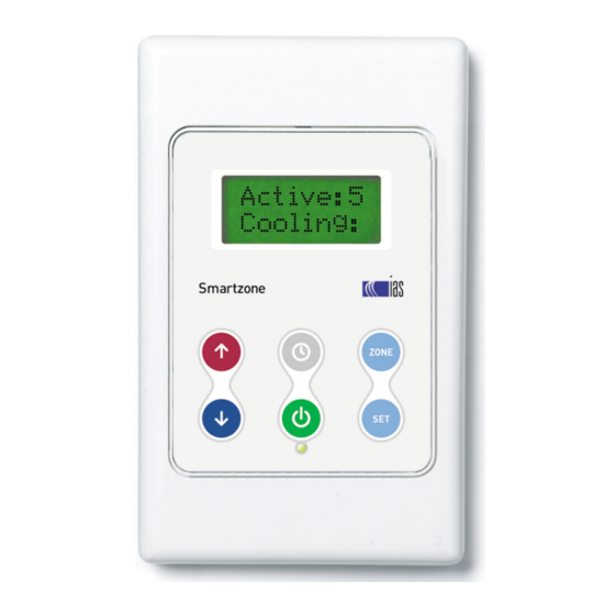
SMARTZONE TECHNICAL MANUAL USER GUIDE SELECTING A ZONE • Press to cycle from the zone summary screen, through each of the individual zone status screens. The zone summary screen is depicted in the image in Section 6.1. ACTIVATING / DEACTIVATING ZONES •... -
Page 25: Setting The Clock
SMARTZONE TECHNICAL MANUAL USER GUIDE • Press to move to the next character. Press to return to the previous character to correct a mistake. • Repeat steps 5 & 6 for all eight character spaces. • Pressing to accept the final character will save the zone name and the controller will return to the standard display. -
Page 26: Appendix Atypical Eight Zone System Setup
SMARTZONE TECHNICAL MANUAL APPENDIX A APPENDIX A TYPICAL EIGHT ZONE SYSTEM SETUP... -
Page 27: Appendix Binnocab Crimping Instructions
SMARTZONE TECHNICAL MANUAL APPENDIX B APPENDIX B INNOCAB CRIMPING INSTRUCTIONS � Never insert uncrimped plugs into the sockets. This may cause damage to the socket contacts. Crimped plugs should insert easily into sockets until the locking tab clicks into place. Plugs that have been incorrectly crimped may be difficult to insert, and may cause damage to the... -
Page 28: Appendix Ccalculating Zone Weights
Consider the following simple example: A Smartzone system is made up of two zones of equal size, with the same zone weight. One zone is fully closed and one zone is fully open. This is equal to the total system being 50% open. - Page 29 SMARTZONE TECHNICAL MANUAL APPENDIX C To determine the zone weight for each zone, multiply the heat load of each zone by the zone weight factor and round to the nearest whole number. E.G. ZW = ZHL x ZWF Record the zone weight for each zone in the space provided.
-
Page 30: Appendix Dtroubleshooting Guide
SMARTZONE TECHNICAL MANUAL APPENDIX D APPENDIX D TROUBLESHOOTING GUIDE PROBLEM POSSIBLE CAUSES / SUGGESTED ACTION Check the cable to touchpad. LCD touchpad is blank. Check the 24VAC power supply from the transformer (If failed see next). Prior to connecting the new transformer, verify the new transformer is capable of supplying 24V @ 48VA. - Page 31 SMARTZONE TECHNICAL MANUAL APPENDIX D PROBLEM POSSIBLE CAUSES / SUGGESTED ACTION Disconnect 24VAC power supply and check that the 1234 module is plugged into the Zone 5 and above do not operate 5678 module. There are no cables between the modules, they plug from one module to correctly.
-
Page 32: Appendix Etechnical Data Sheets
SMARTZONE TECHNICAL MANUAL APPENDIX E APPENDIX E TECHNICAL DATA SHEETS Smartzone Main Processor Module Product Code RC-SZ-PLUS-MPM-IC-EA Outputs Environmental Conditions 1 x Auxilliary Run Relay Transport Connection Type ......2 x Voltage Free Terminal Temperature Range ....0-80°C Maximum load ......1 Ampere Humidity ........ - Page 33 SMARTZONE TECHNICAL MANUAL APPENDIX E Smartzone 1234 Zone Expansion Module Product Code RC-SZ-PLUS-1234-IC-EA Drawing Not to Scale Drawing Not to Scale Environmental Conditions Transport Temperature Range ....0-80°C Humidity ........10-80% Operation Temperature Range ....0-60°C Humidity ........10-80% Communications C Hybrid Bus from Main Processor Module Connection Type ......
- Page 34 SMARTZONE TECHNICAL MANUAL APPENDIX E Smartzone 5678 Zone Expansion Module Product Code RC-SZ-PLUS-5678-IC-EA Drawing Not to Scale Environmental Conditions Transport Temperature Range ....0-80°C Humidity ........10-80% Operation Temperature Range ....0-60°C Humidity ........10-80% Communications C Hybrid Bus from Main Processor Module Connection Type ......
- Page 35 SMARTZONE TECHNICAL MANUAL APPENDIX E Smartzone LCD Touchpad Product Code RC-SZ-PLUS-LCD-IC-EA 72 mm Environmental Conditions Transport Temperature Range ....0-80 °C Humidity ........10-80 % Operation Temperature Range ....0-50 °C Humidity ........10-80 % Communications IASNet Proprietary Bus to Main Processor Module Connection Type ......
- Page 36 SMARTZONE TECHNICAL MANUAL APPENDIX E Room Controller Product Code RC-RC-PLUS-IC-DCC 72 mm Environmental Conditions Transport Temperature Range ....0-80 °C Humidity ........10-80 % Operation Temperature Range ....0-50 °C Humidity ........10-80 % Communications SmartSense to Zone Expansion Modules Connection Type ......
- Page 37 SMARTZONE TECHNICAL MANUAL APPENDIX E Supply Air Sensor Product Code RC-DS-PLUS-IC Drawing not to scale Sensor Type ..........NTC thermistor Resistance ........47 kΩ ± 0.5 kΩ at 25 °C Range ......... 0 °C to 80 °C Thermal Time Constant ....12 seconds Connection Type ......
- Page 38 SMARTZONE TECHNICAL MANUAL APPENDIX E Touchpad Expansion Module Product Code RC-TPAD-EXP-24V-IC Drawing Not to Scale Drawing Not to Scale Environmental Conditions Transport Temperature Range ....0-80°C Humidity ........10-80% Operation Temperature Range ....0-60°C Humidity ........10-80% Power Supply Supply Voltage ......24VAC ± 10% Frequency ........
- Page 40 Product Support Freecall 1800 354 434 www.ias.net.au support@ias.net.au Sales Phone: 1300 306 125 sales@ias.net.au Designed and manufactured in Australia by Innovative Air Systems Pty Ltd...
Need help?
Do you have a question about the Smartzone and is the answer not in the manual?
Questions and answers