Advertisement
V 0.99
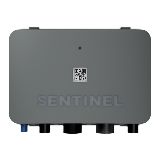
INSTALLATION PARTS - INCLUDED
●
Sentinel Boat Monitor device
●
Installation bracket
●
4 self-tapping screws
●
User manual
●
Warranty
OPTIONAL PARTS
●
Magnetic door switch (SKU:A1012)
●
Bilge float sensor (SKU: A1013)
●
Shore power sensor (SKU: A1009)
●
External GPS antenna with 3m cable (SKU: A1052)
Sentinel
Boat Monitor BM-50
Installation Guide
(Lite, Standard and Pro versions)
Advertisement
Table of Contents

Related Manuals for Sentinel BM-50


Summary of Contents for Sentinel BM-50
- Page 1 V 0.99 Sentinel Boat Monitor BM-50 Installation Guide (Lite, Standard and Pro versions) INSTALLATION PARTS - INCLUDED ● Sentinel Boat Monitor device ● Installation bracket ● 4 self-tapping screws ● User manual ● Warranty OPTIONAL PARTS ● Magnetic door switch (SKU:A1012) ●...
- Page 2 Using the Sentinel App To access the boat's data you need a Sentinel Boat Monitor installed and a Sentinel app for your mobile device. Use Play Store for Android or App Store for iOS and search for “Sentinel boat” app.
- Page 3 8. Scan your QR Code (found on the device or in the installation manual) 9. Input the name of the boat. Before boat’s data can be received you need to activate the Sentinel Boat Monitor Installation Guide Selecting a correct installation spot is essential for optimal device performance.
-
Page 4: Wall Mounting
Wall mounting The BM-50 features an installation bracket that allows simple device installation and replacement. The bracket is fixed to the wall using 4 screws or adhesive tape. Remove the bracket by gently lifting the clips on top of the device (1), and then pull the bracket away from the device. -
Page 5: Electrical Connection Overview
Lite , Standard, Pro Blue Shore Digital input 1 - Shore power** Standard, Pro VIN1/Supply Voltage input 1 - Service battery + BM-50 power supply Lite , Standard, Pro Green Door Digital input 3 - Door sensor** Lite, Standard and Pro... -
Page 6: Power Supply Connection
Relay 1 Contact Standard and Pro * contact Sentinel for more information on supported protocols ** bilge, door, PIR and shore power inputs can be changed to other digital sensor types. Use Web or Mobile App to change sensor type from their default values... - Page 7 Connect the BLACK wire to system ground. Bilge, door switch connection and shore power detection Boat monitor comes with predefined digital input configuration shown on wiring diagram 2.5. If a different configuration is required, digital inputs can be reconfigured in the Sentinel app.
- Page 8 NMEA 2000® connection (Pro and Standard version only) Boat monitor BM-50 is equipped with two CAN interfaces. CAN1 / NMEA2000 connector is a primary NMEA 2000 interface that connects to the boat instrument NMEA2000 backbone. CAN2 interface is a multipurpose CAN interface (Pro version only).
-
Page 9: Typical System Wiring Diagram
Typical system wiring diagram... -
Page 10: Troubleshooting
If the device LED is off, check the fuse and make sure the power supply to the device is higher than 12V! If the issue cannot be resolved, contact Sentinel support by using the report issue feature built into the Sentinel application. -
Page 11: Technical Specification
3.1. Technical specification Parameter Minimum Typical Maximum Supply Voltage 11 V 12 V -32 V 34 V Input resistance of digital and 500 kΩ analog inputs (except power supply) Input Voltage Range: Voltage 1 30 V Voltage 2/3/4 60 V Digital input Voltage threshold Relay switching voltage 60 VDC... - Page 12 Appendix A List of receiving NMEA2000 PGNs PGN ID PGN Name 130316 Temperature Extended Range 65280 Proprietary pgn 65280 130306 Wind Data 127251 Rate of Turn 127257 Attitude 127258 Magnetic Variation 128259 Speed 128267 Water Depth 129026 COG & SOG, Rapid Update 129284 Navigation Data 130310...
Need help?
Do you have a question about the BM-50 and is the answer not in the manual?
Questions and answers