
Summary of Contents for NEWARK CYLINDERS Heat Geek HG Series
- Page 1 V2.0 HG Series Ultra-High Efficiency Cylinders Designed by Available Exclusively, from HG Series V2.0...
-
Page 2: Table Of Contents
Table of Contents 1. Cover page 2. Table of contents 3. Introduction to the HG Series 4. Product Support & Guarantee 5. Key Features 6. Diagram 7. General Specification 8. A Models 9. A Models (continued) 10. B Models 11. Components 12. -
Page 3: Introduction To The Hg Series
Introduction to the HG Series Bespoke hot water cylinder manufacturer, Newark Cylinders, have launched the HG Series - a range of ultra-high efficiency cylinders designed by leading heating experts, Heat Geek. The HG Series has been designed to be the most efficient hot water cylinder available in the UK. -
Page 4: Product Support & Guarantee
Cylinders. Their contact information can be found on the back page of this document. Manufacturer’s Guarantee All HG Series Cylinders are guaranteed by Newark Cylinders for 7 years against manufacturing defects, provided they have been used and maintained in full accordance with the guidance provided in this document. -
Page 5: Key Features
Key Features Ultra-High Efficiency Cylinder 320x230mm steel plate to allow for the mounting of controls and/or product literature Carrying Handles spaced at an ergonomic 90° apart (2 at high level, 2 at low level) 6.0m²* Coil with reverse return temperature- configuration monitoring points... -
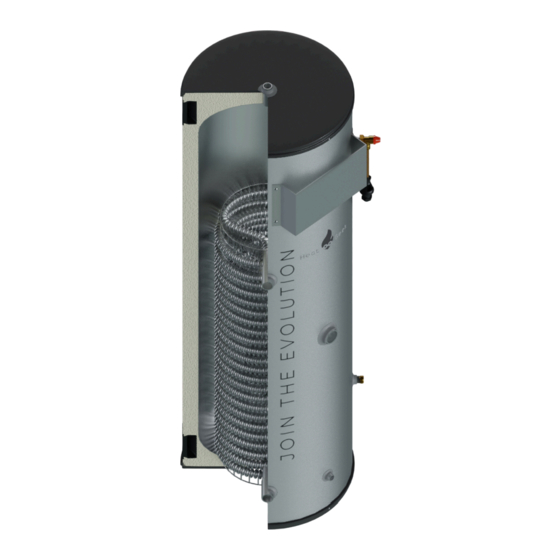
Page 6: Diagram
Example Diagram 1”F BSP Hot Outlet Carry Handles ¾”F BSP for TPRV ½”F BSP with fitted 10mm Pocket Control Mounting Plate (320x230mm) Coil Flow - Variable Connection Size. See Models on pages 8, 9, & 10 to clarify) Coil - Variable size. See Models on pages “F BSP 8, 9, &... -
Page 7: General Specification
General Specification Features which are consistent across all Models All Models within the HG Series have the following features. The Model specifications on pages 8, 9, & 10, detail all of the features which vary between Models. Pressurisation Description: Unvented Heat input Description: Single coil 1.0mm Duplex SS for 375mm &... -
Page 8: A Models
A Models The taller Models (below and on page 9) should be used wherever possible. If, however, the installation space has a height restriction, the Features which vary shorter Model variants (on page 10) are also available. HG150A - As per General Spec. On page 7, plus: Volume: 150L Dimensions Before Insulation &... -
Page 9: A Models (Continued)
A Models (continued) The taller Models (below and on page 8) should be Features which vary used wherever possible. If, however, the installation space has a height restriction, the shorter Model variants (on page 10) are also available. HG350A - As per General Spec. On page 7, plus: Volume: 350L Dimensions Before Insulation &... -
Page 10: B Models
B Models The taller Models (on pages 8 & 9) should be used wherever possible. If, however, the Features which vary installation space has a height restriction, the shorter Model variants (below) are also available. More B Models can potentially be added. -
Page 11: Components
Components Thermostat Pockets x2 A 10mm dry pocket with a ½”M BSP thread, to accommodate control thermostat probes. ½” 5 bar Expansion Relief Valve (for 250L+ Models) Relieves excess system pressure over 6 bar. ¾” 7 bar Temperature & Pressure Relief Valve Releases Hot Water should temperatures exceed 90°C. -
Page 12: Installation Guidance
Installation Guidance Installation should only be carried out by a “competent operative” i.e. the installer must have attended a recognised course in unvented hot water systems. All registered operatives should carry an Identification Card issued by the institute of Unvented Hot Water Systems. The installation area should be able to cope with the weight, incoming pipes and discharge pipe when full. -
Page 13: Installation Guidance (Continued)
Installation Guidance (continued) 5. The TPRV (temperature and pressure relief valve) is set at 90°C and 7 BAR. No valves should be fitted between the relief valves and the cylinder. 6. The tundish, which shows visible discharge from the relief valves, is to be in a prominent, visible and safe position away from any electrical devices . -
Page 14: Discharge Pipework
Discharge Pipework HG Series V2.0 | 14... -
Page 15: Discharge Information
Discharge Information Discharge pipes from safety devices D3.50 Safety devices such as temperature relief valves or combined temperature and pressure relief valves should discharge either directly or by way of a manifold via a short length of metal pipe (D1) to a tundish. 3.51 The diameter of discharge pipe (D1) should be not less than the nominal outlet size of the safety device, e.g. -
Page 16: Discharge Information (Continued)
Discharge Information (continued) 3.57 The discharge pipe (D2) should be made of: a. metal; or b. other material that has been demonstrated to be capable of safely withstanding temperatures of the water discharged and is clearly and permanently marked to identify the product and performance standard (e.g. - Page 17 Discharge Information (continued) If plastic pipes are used as branch pipes carrying discharge from a safety device, they should be either polybutylene (PB) or crosslinked polyethylene (PE-X) complying with national standards such as Class S of BS 7291-2:2006 or Class S of BS7291-3:2000 respectively; and d.
-
Page 18: Commissioning
Commissioning IMPORTANT 1. Ensure the drain at the base of the cylinder is closed. 2. Open a hot tap the furthest distance from the unit. 3. Gradually open the cold mains isolator valve and fill cylinder until water appears at the hot tap. Attend to each hot water outlet in turn and ensure water flow is obtained at each outlet expelling any air within the pipework. -
Page 19: Commissioning Checklist
Commissioning Checklist Fitter Details Cylinder Production No. Commissioned by. Registration Operative No. Approval Licence No. Company Name Company Address Commissioning Date Telephone No. Building Regulations Notification System Type Indirect Boiler Biomass Boiler Heat Pump Solar Panels Direct Electric System Primary Settings Is the circuit sealed or vented? Vented Sealed... -
Page 20: Commissioning Checklist (Continued)
Commissioning Checklist (continued) Final Checks Check The system complies with the appropriate building regulations. The system has been installed and commissioned in accordance with the manufacturers instructions The system controls have been demonstrated to and understood by the customer. The manufacturer’s literature, including benchmark checklist, has been explained and left with the customer. -
Page 21: Troubleshooting
Troubleshooting DISCHARGE FROM EITHER OF THE RELIEF VALVES INDICATES A MALFUNCTION IN THE SYSTEM AND MUST BE INVESTIGATED IMMEDIATELY. OVERHEATED HOT WATER DISCHARGE In the unlikely event of overheated (95°C) water being discharged, the heat source(s) should be switched off immediately and a competent operative called out. -
Page 22: Troubleshooting (Continued)
Troubleshooting (continued) 3. If the gauge shows a pressure in excess of 3 BAR, the pressure reducing valve (if adjustable) may be set too high, or may have developed a fault. If adjustment of the valve doesn’t bring the pressure down to 3 BAR (after opening and re-closing a tap), it should be replaced. - Page 23 Troubleshooting (continued) IMMERSION HEATERS If the immersion heater is not heating the water, the electrical cut- out (or high limit stat) may have operated. This may be due to the control stat being set too high, being miscalibrated, or having developed another fault.
-
Page 24: Servicing
Servicing Annual maintenance and servicing should be carried out by a competent operative. Failure to maintain this system in accordance with these instructions will invalidate the manufacturer’s warranty. We would, therefore, recommend that a regular service schedule is arranged at the time of its installation. All maintenance and servicing work should be recorded on the next page of this booklet. -
Page 25: Servicing Record
Servicing Record Service Date Serviced by Comments HG Series V2.0 | 25... -
Page 26: Manual Handling
Manual Handling As our cylinders can vary in both size and weight, it is important to know the correct way to handle them; Firstly, here are some basic manual handling tips to always keep in mind: It is recommended that any weight over 25kg should be lifted by at least 2 people. -
Page 27: How To Order
How To Order TO PLACE AN ORDER: Please email the following details to sales@newarkcylinders.co.uk: • Your company name and billing address • A delivery address (if different) • Your phone number • A site contact name & phone number (if not you) •...
Need help?
Do you have a question about the Heat Geek HG Series and is the answer not in the manual?
Questions and answers
Heat Transfer rate of the heating coil of the HW HG350A cylinder, for calculating the heating time of HW. Assuming the the flow temp will be 50 deg C from ASHP, and the DT will be 50deg C. The information will help me to calculate the time for the HW cylinder to be heated from 10degC to 60deg C.
forgot to add, that heat transfer coefficient will be in (in watts per square meter per degree Celsius, W/m2 °C)