Table of Contents
Advertisement
Quick Links
Installation and Operation Manual
CONTACT LOCAL BUILDING OR FIRE OFFICIALS ABOUT RESTRICTIONS AND
INSTALLATION INSPECTION REQUIREMENTS IN YOUR AREA.
PLEASE READ THIS ENTIRE MANUAL BEFORE INSTALLATION AND USE OF THIS
PELLET
FUEL-BURNING
INSTRUCTIONS COULD RESULT IN PROPERTY DAMAGE, BODILY INJURY OR EVEN
DEATH.
INSTALLATION BY A PROFESSIONAL IS STRONGLY RECOMMENDED
This manual is available for free download on the manufacturer's web site. It is a copyrighted
document. Re-sale is strictly prohibited. The manufacturer may update this manual from
time to time and cannot be responsible for problems, injuries, or damages arising out of the
use of information contained in any manual obtained from unauthorized sources.
READ AND SAVE THESE INSTRUCTIONS FOR REFERENCE
Printed in Canada
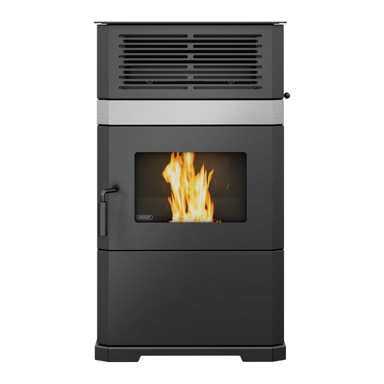
ECO-65R
(DP00061 model)
Safety tested according to ULC S627 and
US Environmental Protection Agency phase
II certified pellet stove compliant with 2020
ROOM
HEATER.
ASTM E1509 by
an accredited laboratory
standard using pellet fuel
EPA ≤ 2.0 g/h
Fabricant de poêles international inc.
250, rue de Copenhague, St-Augustin-de-
Desmaures (Québec) Canada G3A 2H3
After-sale service: 1-877-356-6663
E-mail: tech@sbi-international.com
www.drolet.ca
FAILURE
TO
FOLLOW
THESE
46384A
2024-06-19
Advertisement
Table of Contents

Subscribe to Our Youtube Channel
Related Manuals for Drolet ECO-65R


Summary of Contents for Drolet ECO-65R
- Page 1 Installation and Operation Manual ECO-65R (DP00061 model) Safety tested according to ULC S627 and ASTM E1509 by an accredited laboratory US Environmental Protection Agency phase II certified pellet stove compliant with 2020 standard using pellet fuel EPA ≤ 2.0 g/h Fabricant de poêles international inc.
- Page 2 ECO-65R Installation and Operation Manual THANK YOU FOR CHOOSING THIS DROLET PELLET STOVE As one of North America’s largest and most respected pellet stove, wood stove and fireplace manufacturers, Stove Builder International takes pride in the quality and performance of all its products.
-
Page 3: Table Of Contents
ECO-65R Installation and Operation Manual Table of contents Général informations ECO-65R (DP00061) ................... 5 1.1 About Pellet Heating ..........................5 1.1.1 Top 10 Reasons for Buying a Pellet Stove ................... 5 1.2 Appliance performance ........................6 1.3 General Features ..........................7 1.4 Overall Exterior Dimensions ........................ - Page 4 ECO-65R Installation and Operation Manual 6.7 Signs of an Overheating Stove ......................36 Maintenance ............................37 7.1 Stove Maintenance ..........................37 7.1.1 Recommended Maintenance Schedule ..................37 7.1.2 Cleaning the Baffle, the Heat Exchanger and the Combustion Chamber ........38 7.1.3...
-
Page 5: Général Informations Eco-65R (Dp00061)
ECO-65R Installation and Operation Manual 1 Général informations ECO-65R (DP00061) 1.1 About Pellet Heating Pellet stoves offer a dramatic improvement in the convenience of heating with solid fuel. Wood pellets are handled in bags and are therefore easily and cleanly stored. A single loading of a pellet stove can provide long hours of warmth. -
Page 6: Appliance Performance
ECO-65R Installation and Operation Manual 1.2 Appliance performance Fuel type Wood Pellet (Premium grade or better) ☨ Recommended heating area 800 to 2,600 ft (74 to 242 m Hopper capacity 125 lb (57 kg) Maximum burn time 105 h Maximum heat input rate 37,895 BTU/h (11.1 kW) -
Page 7: General Features
ECO-65R Installation and Operation Manual 1.3 General Features 4 po (see Section 4.3: Equivalent Vent Length Recommended chimney diameter (EVL)) Flue outlet diameter 4 po (100 mm) Type of chimney ULC/ORD-C441, CAN/ULC S609, UL 641 (TYPE L) Baffle material Stainless Steel... -
Page 8: Overall Exterior Dimensions
ECO-65R Installation and Operation Manual 1.4 Overall Exterior Dimensions FRESH AIR INTAKE FLUE OUTLET... -
Page 9: Part A - Installation
ECO-65R Installation and Operation Manual PART A – INSTALLATION 2 Installation Safety Information 2.1 Installation Warnings, Cautions and Recommendations PROFESSIONNAL INSTALLATION IS HIGHLY RECOMMENDED. YOU MAY NEED TO OBTAIN A BUILDING PERMIT FOR THE INSTALLATION OF THIS STOVE AND ITS VENTING SYSTEM. CONSULT YOUR MUNICIPAL BUILDING DEPARTMENT OR FIRE DEPARTMENT BEFORE INSTALLATION TO DETERMINE THE NEED TO OBTAIN ONE. - Page 10 ECO-65R Installation and Operation Manual DO NOT CONNECT TO OR USE IN CONJUNCTION WITH ANY AIR DISTRIBUTION DUCTWORK. THE VENTING SYSTEM MUST BE COMPLETELY AIRTIGHT AND PROPERLY INSTALLED. ALL VENT CONNECTOR JOINTS MUST BE SEALED AND FASTENED IN ACCORDANCE WITH THE PELLET VENT MANUFACTURER'S INSTRUCTIONS TO ENSURE CONSISTENT PERFORMANCE AND AVOID SMOKE AND ASH SPILLAGE.
-
Page 11: Regulations Covering Pellet Stove Installation
ECO-65R Installation and Operation Manual 2.2 Regulations Covering Pellet Stove Installation When installed and operated as described in these instructions, this pellet stove is suitable for use as a freestanding heater in residential installations. In Canada, the CSA B365 Installation Code for Solid Fuel Burning Appliances and Equipment and the CSA C22.1 Canadian National Electrical Code are to be followed in the absence of... -
Page 12: Clearances To Combustible Material
ECO-65R Installation and Operation Manual 3 Clearances to Combustible Material The clearances shown in this section have been determined by tests according to procedures set out in safety standards ULC S627 (Canada), ASTM E1509 (U.S.A). When the pellet stove is installed so that its surfaces are at, or beyond, the minimum clearances specified, combustible surfaces will not overheat under normal and even abnormal operating conditions. -
Page 13: Floor Protection
ECO-65R Installation and Operation Manual 3.3 Floor Protection For floor protection clearances refer to the following table. FLOOR PROTECTION LETTER CANADA 18″ (460 mm)** 6″ (155 mm) N/A (USA only) 6″ (155 mm) N/A (Canada 8″ (205 mm) only) N/A (Canada 8″... -
Page 14: Venting System
ECO-65R Installation and Operation Manual 4 Venting system 4.1 General Even though the chimney draft is mechanical, a suitable venting system will ensure a natural draft which will prevent smoke spillage in your home if a power outage occurs. Moreover, a suitable venting system configuration will help getting the best efficiency out of your stove when installed in accordance with the required EVL (see Section 4.3: Equivalent Vent Length... - Page 15 ECO-65R Installation and Operation Manual Here is an example to help you calculate Equivalent Vent Length. On the following figure the EVL can be calculated like this: 2 horizontal run of 1’ = (2 X 1’) X 1’ = 2’ of EVL ...
-
Page 16: Termination Location
ECO-65R Installation and Operation Manual 4.4 Termination Location Termination should not be located so that hot exhaust gases can be a hazard. They can reach temperatures of 500°F (260°C) and cause serious burns. CAUTION: TERMINATION COLLAR (SPARK ARRESTER) IS MANDATORY. - Page 17 ECO-65R Installation and Operation Manual Canada: Min. Letter Description clearances Clearances above grade level or any adjacent surface that might 12’’ (30 cm) support snow, ice, or debris 39’’ (100 cm) Clearance to window or door that may be opened 39’’...
-
Page 18: Installation Configurations
ECO-65R Installation and Operation Manual 4.5 Installation Configurations 4.5.1 Installation Warnings, Cautions and Recommendations Reminder PROFESSIONNAL INSTALLATION IS HIGHLY RECOMMENDED THIS STOVE USES A PRESSURIZED VENTING SYSTEM. ALL VENT CONNECTOR JOINTS MUST BE SEALED AND FASTENED. CONSULT THE PELLET VENT MANUFACTURER’S... -
Page 19: Through Wall Installation (Main Floor Or Basement)
ECO-65R Installation and Operation Manual 4.5.2 Through Wall Installation (Main Floor or Basement) 1. Position appliance following clearances vent manufacturer’s instructions 2. Install a stove adapter or a stove adapter tee onto the appliance flue collar. 3. . Locate the position of the exhaust pipe in the wall and cut a hole of the appropriate size for vent in the wall. -
Page 20: Through Roof Installation
ECO-65R Installation and Operation Manual 4.5.3 Through Roof Installation 1. Position appliance following clearances following vent manufacturer’s instructions. 2. Install a stove adapter or a stove adapter tee onto the appliance flue collar. If necessary, use a horizontal additional length between the flue outlet and the tee. -
Page 21: Through A Factory Built Chimney
ECO-65R Installation and Operation Manual 4.5.4 Through a Factory Built Chimney To make an installation through a factory built chimney, run a 4" stainless steel liner inside the factory built chimney. 1. Position stove following clearances given following vent manufacturer’s instructions. -
Page 22: Through An Existing Masonry Fireplace
ECO-65R Installation and Operation Manual 4.5.5 Through an Existing Masonry Fireplace 1. Position stove, following clearances and following vent manufacturer’s 12”-18” instructions 2. Build and Install a blocking plate inside the chimney to seal the fireplace damper. Stainless steel plate and screws are recommended. -
Page 23: Through An Existing Masonry Chimney
ECO-65R Installation and Operation Manual 4.5.6 Through an Existing Masonry Chimney 1. Position stove following clearances following vent manufacturer’s 12”-18” instructions. 2. Mark the center of the hole where the vent pipe will go through the masonry chimney. 3. It is necessary to make a hole in the... -
Page 24: Factory-Built Metal Chimneys In Mobile Homes
ECO-65R Installation and Operation Manual 4.5.7 Factory-Built Metal Chimneys in Mobile Homes For use in a mobile home in Canada, this pellet stove must be connected to a vent system certified according to the standard or ULC/ORD-C441 or CAN/ULC-S609. vent system meeting the requirements of ULC S629 can also be used for 650°C Factory-built chimney. -
Page 25: Part B - Operation
ECO-65R Installation and Operation Manual PART B - OPERATION 4.6 General Information 4.7 Operation Warnings, Cautions and Recommendations KEEP THIS MANUAL FOR REFERENCE. DURING THE FIRST FEW FIRES, YOUR STOVE WILL EMIT AN ODOR AND A SMALL AMOUNT OF FUMES AS THE HIGH TEMPERATURE PAINT CURES OR BECOMES SEASONED TO THE METAL. - Page 26 ECO-65R Installation and Operation Manual NEVER TRY TO REPAIR OR REPLACE ANY PART OF THE STOVE UNLESS INSTRUCTIONS ARE GIVEN BY THE MANUFACTURER. ALL OTHER WORK SHOULD BE DONE BY A TRAINED TECHNICIAN. DO NOT OPERATE THE STOVE IF THE FLAME BECOMES DARK AND SOOTY OR IF THE BURN POT OVERFILLS WITH PELLETS.
-
Page 27: Zone Heating And How To Make It Work For You
ECO-65R Installation and Operation Manual OPERATION, THE ASH CONTENT OF THE PELLET FUEL SHOULD BE LESS THAN 1% AND THE CALORIFIC VALUE APPROXIMATELY 8,500 BTU/LB. OTHERS FUELS WITH A HIGH ASH CONTENT WILL REQUIRE A HIGHER LEVEL OF MAINTENANCE AND CLEANING. -
Page 28: Combustible
ECO-65R Installation and Operation Manual Although the stove may be able to heat the main living areas of your house to an adequate temperature, this stove must serve as a supplementary heat source. You should have a conventional oil, gas or electric additional heating system to provide heating in the home. The manufacturer cannot be responsible for additional heating costs associated with the use of an alternative heat source in case of stove failure or power outage. -
Page 29: Where To Store Bags Of Pellets
ECO-65R Installation and Operation Manual DO NOT BURN : COAL; SALT WATER DRIFTWOOD OTHER PREVIOUSLY SALT WATER GARBAGE; LAWN CLIPPINGS OR YARD WASTE; SATURATED MATERIALS; UNSEASONED WOOD; OR MATERIALS CONTAINING RUBBER, INCLUDING TIRES; PAPER PRODUCTS, CARDBOARD, PLYWOOD, OR PARTICLE BOARD. -
Page 30: Stove Controls
ECO-65R Installation and Operation Manual 5 Stove Controls 5.1 Control Panel The blowers and automatic fuel supply are controlled from a control panel (A) on the right-hand side of the ECO-65R. The control panel functions are as follows:... -
Page 31: Mode Button
ECO-65R Installation and Operation Manual Control panel screen Operation mode : THERMOSTAT: Thermostatic control MANUAL (optional) Button to select Button to clear between modes most error codes Button to change the Button to feed and start convection fan speeds when the auger is empty Pellet burn rate Button + and –... -
Page 32: Fuel Feed Button
ECO-65R Installation and Operation Manual 5.1.2 Fuel Feed Button When the “Fuel Feed” button is pushed the stove will feed pellets continuously into the burn pot during 90 seconds and then the ignition cycle will begin. The “Feed and Start” message will appear. -
Page 33: Adjustments
ECO-65R Installation and Operation Manual 5.2 Adjustments 5.2.1 Selecting the Combustion Level (Heat Rate) The heat input of the stove varies between 9,000 BTU/h to 39,000 BTU/h. To change the combustion level select the + or – button when the stove is in function. -
Page 34: Stove Operation
ECO-65R Installation and Operation Manual 6 Stove Operation 6.1 First Startup Before starting your stove, make sure that the burn pot, the baffle and the maintenance access panels are properly installed. Make sure that the stove has been emptied of all tools and accessories (see Section 2.3: Before Operating Your Stove). -
Page 35: Refueling
ECO-65R Installation and Operation Manual 6.4 Refueling While the stove is running, you have up to 3 minutes to refill the hopper with pellets. Note that opening the hopper lid will stop the auger from feeding pellets to the stove. If the hopper lid is... -
Page 36: Signs Of An Overheating Stove
ECO-65R Installation and Operation Manual one of these logics, you need to change the setting to PILOT ON or PILOT OFF by simultaneously pressing the following two buttons on the PC Board for a couple of seconds: Once you do that, the letters P, I, L, O, T, O, N will appear on the PC Board to let you know that you are in the “PILOT ON”... -
Page 37: Maintenance
ECO-65R Installation and Operation Manual 7 Maintenance 7.1 Stove Maintenance 7.1.1 Recommended Maintenance Schedule Use this as a guide when used under average conditions. Daily Weekly Twice a year Annually or after Components or after or after ± 50 pounds ±... -
Page 38: Cleaning The Baffle, The Heat Exchanger And The Combustion Chamber
ECO-65R Installation and Operation Manual PENDING FINAL DISPOSAL. IF THE ASHES ARE DISPOSED OF BY BURIAL IN SOIL OR OTHERWISE LOCALLY DISPERSED, THEY SHOULD BE RETAINED IN THE CLOSED CONTAINER UNTIL ALL CINDERS HAVE BEEN THOROUGHLY COOLED. 7.1.2 Cleaning the Baffle, the Heat Exchanger and the Combustion Chamber Cleaning the baffle must be done regularly (see Section 7.1.1: Recommended Maintenance... - Page 39 ECO-65R Installation and Operation Manual Using the provided sweeping rod, sweep up and down each exchanger. Make sure you go all the way down to the bottom. Using a scraper, remove all combustion residues that are blocking the baffle holes.
-
Page 40: Exhaust Channel And Exhaust Blower Maintenance
ECO-65R Installation and Operation Manual Reinstall the access panel to the combustion chamber and tighten the wing nuts. DO NOT USE PLIERS OR OTHER TOOLS TO TIGHTEN THE WING NUTS. IT IS HIGHLY RECOMMENDED TO CLEAN THE EXHAUST CHANNEL (SEE SECTION 7.1.3: EXHAUST CHANNEL AND EXHAUST BLOWER MAINTENANCE) IMMEDIATLY... - Page 41 ECO-65R Installation and Operation Manual To remove the two access panels, you must unscrew the wing nuts (A) and then remove the panels (B). Locate the two openings. Clean any dirt or ash buildup from exhaust channels using the scraper supplied with the stove.
-
Page 42: Cleaning The Burn Pot
ECO-65R Installation and Operation Manual 7.1.4 Cleaning the Burn Pot The burn pot must remain clean and the holes should not be obstructed by combustion residues (ashes or clinkers). 1. Clean the burn pot using the scraper provided with the stove or a smaller one. - Page 43 ECO-65R Installation and Operation Manual 3. If necessary, clean the air intake channel. To reach the air intake channel clean out trap, open the ash drawer access door and remove the ash drawer (A). 4. Unscrew the wing nut (C) to open the clean out trap (B). Vacuum the combustion residues.
-
Page 44: Ash Removal
ECO-65R Installation and Operation Manual 7.1.5 Ash Removal 1. To empty the ash drawer (A) of its contents, open the ash drawer access door. Remove the two wing nuts and take out the ash drawer. 2. Empty the ash drawer, vacuum around the drawer and at the bottom of the combustion chamber. -
Page 45: Glass Car
ECO-65R Installation and Operation Manual 7.1.7 Glass Car Clean door glass when necessary. The use of a stove glass cleaner is recommended. Regular household glass cleaners will not remove creosote properly. WARNING: NEVER USE ABRASIVE CLEANERS ON THE GLASS OR ON ANY PLATED PART. -
Page 46: Gasket Replacement
ECO-65R Installation and Operation Manual Remove the handle stop, by unscrewing the two 11/32’’ nuts. Then unscrew the handle one turn to increase the pressure between the door frame and the firebox. Reinstall the handle stop next. 7.1.11 Gasket replacement It is important to replace the gasket with another having the same diameter and density to maintain a good seal. -
Page 47: Venting System Maintenance
ECO-65R Installation and Operation Manual 7.2 Venting System Maintenance Establish a routine for the fuel, wood burner and firing technique. Check daily for creosote build-up until experience shows how often you need to clean to be safe. Be aware that the hotter the fire the less creosote is deposited, and weekly cleaning may be necessary in mild weather even though monthly cleaning may be enough in the coldest months. -
Page 48: Troubleshooting
ECO-65R Installation and Operation Manual 8 Troubleshooting When you have issues with your stove, your first reaction may be to call technical support. This section will help you save time and money by enabling you to solve simple problems by yourself. -
Page 49: Testing A Component
ECO-65R Installation and Operation Manual 8.2 Testing a Component If you suspect that an electrical component to be defective, you can test it by following the procedure given below. Note that you will be able to test only components when the stove is OFF and that all the components are no more in function. - Page 50 ECO-65R Installation and Operation Manual Push the control key to proceed. The frequency of the power source is displayed. Push any control key to proceed. The voltage of the power source is displayed. Push any control key to proceed. Displays if polarity is good (POLP) If polarity is reversed (POLF).
- Page 51 ECO-65R Installation and Operation Manual Displays the temperature read by the flue gas temperature probe. Push any control key to proceed. Convection blower test. Push the control key to proceed. Combustion blower test. Push the control key to proceed. Exhaust blower test.
-
Page 52: Main Error Codes, Possible Causes And Solutions
ECO-65R Installation and Operation Manual 8.3 Main Error Codes, Possible Causes and Solutions WARNING: RISK OF ELECTRICAL SHOCK. IF YOU NEED TO MANUALLY TEST, MANIPULATE OR REPLACE ANY COMPONENTS, THE STOVE NEEDS TO BE DISCONNECTED FROM THE WALL OUTLET. This section contains main error codes, possible causes and many suggestions to guide you in resolving them. - Page 53 ECO-65R Installation and Operation Manual ALARM CODES CHART MESSAGE CORRESPONDING WARNING Pressure switch warning. Warning caused by the automatic L-250 sensors: it is located over the pellet housing. Hopper is empty Lighting warning. Hopper lid stayed open more than 3 minutes.
-
Page 54: P Code
ECO-65R Installation and Operation Manual 8.3.1 P Code STOVE SHUTS OFF AND APPEARS ON CONTROL BOARD Possible Remedies: (Unplug stove first when Possible Causes: possible) 1. Pressure tap (located on the Pull off the air hose from the exhaust blower pressure exhaust blower) is blocked. -
Page 55: H Code
ECO-65R Installation and Operation Manual 8. Pressure switch is defective Even though this situation is highly unlikely, it’s (very rare). possible the pressure switch is defective. To test the airflow pressure switch, you need to disconnect the air hose from the blower casing. With the other end still... - Page 56 ECO-65R Installation and Operation Manual Heat Exchanger and the Combustion Chamber). 7. The convection blower is defective. See Section 8.2: Testing a Component and test the convection blower. 8. he combustion blower needs cleaning. Carefully clean blower housing and make sure blower louvers are not blocked.
-
Page 57: E Code
ECO-65R Installation and Operation Manual 8.3.3 E Code STOVE SHUTS OFF AND DISPLAYS WARNING CODE Possible Remedies: (Unplug stove first when Possible Causes: possible) 1. The stove ran out of pellets. Refill the hopper. Erase the error code and press the auger button (see Section 5.1.2: Fuel Feed... - Page 58 ECO-65R Installation and Operation Manual 5. The flue gas temperature probe is The probe is a heat sensor located on the exhaust defective. channel. Its function is to tell the control board that the stove has ignited properly by measuring the heat at the exhaust.
- Page 59 ECO-65R Installation and Operation Manual HOPPER AUGER Screws Auger and motor assembly gasket BURN POT AUGER Screws Auger and motor assembly GASKET...
-
Page 60: L Code
ECO-65R Installation and Operation Manual 8.3.4 L Code STOVE FEEDS PELLETS, BUT WILL NOT IGNITE AND APPEARS ON THE CONTROL BOARD Possible Causes: Possible Remedies: 1. Inadequate fuel is used. Remove the burn pot, make sure that all openings are clear and check that no ash has filled the tube around the igniter. -
Page 61: Code
ECO-65R Installation and Operation Manual 8.3.5 d Code STOVE STOPS FEEDING PELLETS AND APPEARS ON THE CONTROL BOARD Possible Cause: Possible Remedy: 1. The hopper lid has stayed open for more As a security measure, the auger stops than 3 minutes. -
Page 62: I Code
ECO-65R Installation and Operation Manual 8.3.8 I Code STOVE FEEDS PELLETS, BUT WILL NOT IGNITE AND APPEARS ON THE CONTROL BOARD Possible Cause: Possible Remedy: 1. The igniter fuse on the Test the resistance (ohms, Ω) with a multimeter. If the control board has blown. -
Page 63: Smoke Smell
ECO-65R Installation and Operation Manual 2. The wiring Make sure the auger motor wiring is properly connected and not shorted. harness shorted. 8.3.10 Smoke Smell SMOKE SMELL COMING BACK INTO THE HOME Possible Causes: Possible Remedies: 1. Venting system leaks. -
Page 64: Auger Motor Stops Momentarily
ECO-65R Installation and Operation Manual 8.3.11 Auger Motor Stops Momentarily AUGER MOTOR STOP FEEDING PELLETS AND COMES BACK ON Possible Cause: Possible Remedy: 1. The auger motor is overheating and It’s possible that the auger is jammed. tripping the internal temperature shutoff Remove it from its housing (see drawing (thermal protector). -
Page 65: No Display
ECO-65R Installation and Operation Manual 4. Air intake channel is Visually inspect the air intake channel that leads to the burn pot for restricted. foreign material. Make sure that the air-intake shutter is functional and free of any obstruction. 5. The See Section 8.2: Testing a Component and test the combustion... -
Page 66: Wiring Diagram
ECO-65R Installation and Operation Manual 9 Wiring Diagram... -
Page 67: Access To Fuses
ECO-65R Installation and Operation Manual 10 Access to Fuses WARNING: UNPLUG THE STOVE BEFORE CHANGING THE FUSES. All fuses are located inside the housing of the electronic board; the housing is on the back of your stove. Unplug your stove, remove the screw and turn the four spring clips to open... - Page 68 ECO-65R Installation and Operation Manual LETTER FUSE FUNCTION AMPERAGE MAIN BOARD FUSE 7.5A CONVECTION BLOWER COMBUSTION BLOWER EXHAUST BLOWER TOP AUGER #1 BOTTOM AUGER #2 IGNITOR...
-
Page 69: Components Location
ECO-65R Installation and Operation Manual 11 Components Location LETTER COMPONENT HEAT EXCHANGER TUBES BURN POT IGNITOR CONVECTION BLOWER EXHAUST TEMPERATURE PROBE L-250 THERMAL SWITCH HOPPER CONTROL PANEL HOPPER SAFETY SWITCH PRESSURE SWITCH F-160 THERMAL SWITCH POWER CORD RECEPTACLE THERMOSTAT TERMINAL BLOCK... -
Page 70: Blower Replacement
ECO-65R Installation and Operation Manual 12 Blower Replacement CONVECTION BLOWER Unplug the stove. Remove both side panels to access blower. (1) Unscrew the ground A. Disconnect the fan from the harness. Unscrew the four-blower anchor bolt B. (2) Slide the... - Page 71 ECO-65R Installation and Operation Manual COMBUSTION BLOWER Remove the 9 screws (A) and the bottom grille (B). Unlatch the clamps (C). Remove the back draft shutter (G) and the gasket (D). Pull the combustion blower (F) and unplug the wire connector from the harness. Remove the plug...
- Page 72 ECO-65R Installation and Operation Manual EXHAUST BLOWER Remove the left panel.
- Page 73 ECO-65R Installation and Operation Manual Disconnect the exhaust motor (A) and exhaust temperature probe (B) connections. Disconnect the silicone tube from the pressure sensor (C).
- Page 74 ECO-65R Installation and Operation Manual Remove the clamp (D). Remove the access panel (E).
- Page 75 ECO-65R Installation and Operation Manual Remove the screw (F) located in the opening of the trapdoor. Remove the duct assembly (G).
- Page 76 ECO-65R Installation and Operation Manual Remove the bolts (H) and nuts (I) to remove the exhaust blower (J)
-
Page 77: 250 And F-160 Thermal Switch Replacement
ECO-65R Installation and Operation Manual 13 L-250 and F-160 Thermal Switch Replacement L-250 1. Remove both retaining screws (A) holding the thermal switch support bracket (B). 2. Lift up the support bracket. Rotate the bracket 90° clockwise then pull the bracket toward... - Page 78 ECO-65R Installation and Operation Manual Remove the faulty thermal switch. Replace new thermal switch (D) underneath the bracket (B) by means of 2 screws (C). F-160 Unscrew both screws (B) and take out the thermal switch F-160 (A).
-
Page 79: Exploded View And Replacement Parts
ECO-65R Installation and Operation Manual 14 Exploded View and Replacement Parts SECTION A... - Page 80 ECO-65R Installation and Operation Manual SECTION B...
- Page 81 ECO-65R Installation and Operation Manual SECTION C...
- Page 82 ECO-65R Installation and Operation Manual SECTION D...
- Page 83 ECO-65R Installation and Operation Manual SECTION E...
- Page 84 ECO-65R Installation and Operation Manual SECTION F SECTION G...
- Page 85 ECO-65R Installation and Operation Manual SECTION H AND I...
- Page 86 ECO-65R Installation and Operation Manual SECTION J SECTION K...
- Page 87 ECO-65R Installation and Operation Manual IMPORTANT: THIS IS DATED INFORMATION. When requesting service or replacement parts for your stove, please provide the model number and the serial number. We reserve the right to change parts due to technology upgrade or availability. Contact an authorized dealer to obtain any of these parts.
- Page 88 ECO-65R Installation and Operation Manual Item Description SE67242 ASH PAN SE67225 ASH PAN ASSEMBLY SE67018 EXHAUST ADAPTER PIPE 30762 VENT ADAPTER SECURE CLAMP 21392 EXHAUST ADAPTER GASKET 30093 BOLT 1/4-20 X 3/4" HEX GRADE 5 44193 EXHAUST FAN 21393 EXHAUST BLOWER GASKET...
- Page 89 ECO-65R Installation and Operation Manual Item Description 30185 17/64" AA TYPE WASHER BLACK 30335 BLOWER ANTIVIBRATION CUSHION SE75656 LEXAN BOARD BOX 30050 LEVELING BOLT 3/8-16 X 1 1/2" 60036 THERMOSTAT TERMINAL 60196 POWER CORD RECEPTACLE 30138 METAL SCREW #6 3/8'' QUADREX ''A'' TYPE BLACK...
-
Page 90: Appendix A: Horizontal And Vertical Vent Chart
ECO-65R Installation and Operation Manual APPENDIX A: HORIZONTAL AND VERTICAL VENT CHART Possible Horizontal vent length (feet) For example, let’s imagine an installation consisting of a horizontal vent coming out at the back of the stove on a total distance of 8 feet. - Page 91 ECO-65R Installation and Operation Manual Instead, if the installation consisted of a horizontal vent coming out at the back of the stove on a total distance of 4 feet, followed by a tee and a 6-foot vertical rise, it would be acceptable. The...
-
Page 92: Appendix B: Installing A Thermostat (Ac05558)
ECO-65R Installation and Operation Manual APPENDIX B: INSTALLING A THERMOSTAT (AC05558) Using a thermostat will help you maintain a constant temperature throughout the house. A low voltage thermostat (24 volts) is required. A fixed wall mount or hand held model can be used. - Page 93 ECO-65R Installation and Operation Manual Wired thermostat Before installing the thermostat, unplug the power cord from the power outlet. First, connect the two thermostat wires to the terminal block located at the rear on the right hand side of the stove when facing it. Loosen the two middle screws and insert the wires in the terminals.
- Page 94 ECO-65R Installation and Operation Manual Wireless thermostat If you are using a wireless thermostat or a hand held thermostatic remote control, connect the two thermostat wires to the terminal block located at the rear on the right hand side of the stove while facing it.
-
Page 95: Appendix C: Mobile Home Installation
ECO-65R Installation and Operation Manual APPENDIX C: MOBILE HOME INSTALLATION Anchor the stove WARNING: FOR MOBILE HOME INSTALLATION, IT IS MANDATORY TO CONNECT THE STOVE TO AN OUTSIDE COMBUSTION AIR SOURCE. (SEE APPENDIX D: COMBUSTION AIR SUPPLY). When installed in a mobile home, the stove must be anchored to the floor with two screws. - Page 96 ECO-65R Installation and Operation Manual Fresh air intake Pellet pipe length and/or slip section Ceiling support Attic insulation shield Roof flashing Storm collar Pellet pipe length Vertical rain cap...
-
Page 97: Appendix D: Combustion Air Supply
ECO-65R Installation and Operation Manual APPENDIX D: COMBUSTION AIR SUPPLY WARNING: FOR MOBILE HOME INSTALLATION, IT IS MANDATORY TO CONNECT THE STOVE TO AN OUTSIDE COMBUSTION AIR SOURCE. INSULATED PIPE SHOULD NEVER EXCEED 10 FEET. It is recommended to install an outside air inlet in or near the room where the stove is installed. - Page 98 ECO-65R Installation and Operation Manual exposing the flexible pipe. Attach the flexible pipe using pipe clamps(C). For a better seal, you may also use aluminum tape. Wrap the tape around the joint between the flexible pipe and the air inlets. Carefully push the insulation and plastic cover back over the pipe. Fix the plastic in place using aluminum tape.
- Page 99 ECO-65R Installation and Operation Manual Sources of Outside Combustion Air WARNING: IT IS FORBIDDEN TO DRAW COMBUSTION AIR FROM A BASEMENT, AN ATTIC, A GARAGE OR ANY CONFINED SPACE. You can draw air from a ventilated crawl space underneath the floor.
-
Page 100: Appendix E: Optional Hot Air Plenum Kit (Ac01225)
ECO-65R Installation and Operation Manual APPENDIX E: OPTIONAL HOT AIR PLENUM KIT (AC01225) The hot air plenum kit AC01225 is available at your local dealer. Note that the 5-inch round ducts required to complete the installation are sold separately. - Page 101 ECO-65R Installation and Operation Manual This hot air plenum kit contains the following parts: (A) -PL66837 (B) -PL75648 (C) -PL75649 (D) -30100 (E) -30185...
-
Page 102: Drolet Limited Lifetime Warranty
Labour cost and repair work to the account of the manufacturer are based on a predetermined rate schedule and must not exceed the wholesale price of the replacement part. Shall your unit or a components be defective, contact immediately your DROLET dealer. To accelerate processing of your warranty claim, make sure to have on hand the following information when calling: ...
Need help?
Do you have a question about the ECO-65R and is the answer not in the manual?
Questions and answers