Table of Contents
Advertisement
Quick Links
Serial No.: H-A030-E-06
Rotary damper
Pneumatic Actuated Type TA
40〜600mm
Userʼs Manual
Thank you for choosing our product.
This Userʼs manual contains important information for safe use of our
product, so please be sure to read it before handling the product.
After reading this manual, please be sure to keep it in a place where the
user can see it at any time.
[User's Manual] Rotary damper Pneumatic actuated Type TA 40〜600mm
- 1 -
Advertisement
Table of Contents

Related Manuals for AsahiAV TA2A-050D

Summary of Contents for AsahiAV TA2A-050D
- Page 1 Serial No.: H-A030-E-06 Rotary damper Pneumatic Actuated Type TA 40〜600mm Userʼs Manual Thank you for choosing our product. This Userʼs manual contains important information for safe use of our product, so please be sure to read it before handling the product. After reading this manual, please be sure to keep it in a place where the user can see it at any time.
- Page 2 Serial No.: H-A030-E-06 -SAFETY PRECAUTIONS- This Userʼs manual is written on the assumption that the person who handles our products has a basic knowledge of our products, electrical equipment, machinery, control, etc., and it contains technical terms depending on the handling contents. Please read this manual carefully and fully understand the contents and observe the safety precautions for proper use.
-
Page 3: Table Of Contents
Serial No.: H-A030-E-06 Table of contents 1. Our product warranty coverage ··························································································· 4 Applicable to ..................................4 Warranty Period ................................. 4 Guaranteed range ................................4 Disclaimer ................................... 4 2. Safety Instructions ················································································································ 5 Unpacking, Transportation and Storage ........................5 Product Handling ................................6 3. -
Page 4: Our Product Warranty Coverage
Serial No.: H-A030-E-06 1. Our product warranty coverage Unless otherwise stated in the Contract or Specifications, etc., the warranty for the piping material products (hereinafter referred to as "applicable products") such as valves manufactured or sold by us is as follows. Applicable to This warranty applies only when the product is used in Japan. -
Page 5: Safety Instructions
Serial No.: H-A030-E-06 2. Safety Instructions Unpacking, Transportation and Storage Serious injury can result. Prohibition ▶ When hanging or slinging a valve, pay sufficient attention to safety, and do not enter under the load. The valve can be damaged, or leak. Prohibition ▶... -
Page 6: Product Handling
Serial No.: H-A030-E-06 Product Handling Serious injury can result. Prohibition ▶ Do not disassemble the actuator. ▶ Do not touch moving parts during operation with hands, feet or tools. There is a danger of injury. Forcing ▶ If positive pressure gas is used for our resin piping material, a dangerous condition may occur due to the repulsive force peculiar to compressible fluids even if the pressure is the same as the water pressure. - Page 7 Serial No.: H-A030-E-06 There is a danger of injury. Forcing ▶ Use the supplied handle or a tool specified by the manufacturer for manual operation. ▶ When performing manual operation, make sure that the actuator is not operated by the motor.
-
Page 8: Name Of Each Part
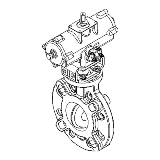
Serial No.: H-A030-E-06 3. Name of each part 40mm〜350mm (Body material: PVC, PP) ※The Size 450mm〜600mm is slightly different. Body Stem Holder (A) [37a] Screw (C) Disc [30] Stand [38] Bolt (E) O-ring (C) [35] Actuator [39] Bolt/nut (A) Stem [37] Joint [157]... - Page 9 Serial No.: H-A030-E-06 400〜600mm (Body material: PP) ※The Size 450mm〜600mm is slightly different. Body [30] Stand [38] Bolt (E) Disc [35] Actuator [39] Bolt/nut (A) O-ring (C) [37] Joint Stem [37a] Screw (C) [User’s Manual] Rotary damper Pneumatic actuated Type TA 40〜600mm - 9 -...
- Page 10 Serial No.: H-A030-E-06 40〜600mm (Body material: PVDF) ※The Size 450mm〜600mm is slightly different. Body [13] Spacer (A) [37] Joint (A) Disc [14] Ground [38] Bolt (E) Stem [15] Screw (A) [39] Bolt/nut (A) [10] Bush (A) [30] Stand [47] Speed controller [12] V packing [35]...
-
Page 11: Product Specifications
Serial No.: H-A030-E-06 4. Product Specifications Model number table [User’s Manual] Rotary damper Pneumatic actuated Type TA 40〜600mm - 11 -... -
Page 12: Relationship Between Maximum Allowable Pressure And Temperature
Serial No.: H-A030-E-06 Relationship between maximum allowable pressure and temperature [User’s Manual] Rotary damper Pneumatic actuated Type TA 40〜600mm - 12 -... -
Page 13: Actuator
Size Actuator pressure Air supply Operation adjustment N/open/clos (mm) model Range port Size range MPa{kgf/cm (0.4MPa) 0.4〜0.7 40〜100 TA2A-050D ±5° Rc 1/4 {4.1〜7.1} 0.4〜0.7 TA2A-080D ±5° Rc 1/4 {4.1〜7.1} Double 0.4〜0.7 200〜300 TA2A-100D ±5° Rc 1/4 acting {4.1〜7.1} 0.4〜0.7 TA2A-125D ±5°... -
Page 14: Standard Option
Serial No.: H-A030-E-06 Standard option Solenoid valve Power Piping Effective Operation Size (mm) Model code consumpti Additional functions port Size area Double ○Built-in bypass valve acting AC ; 6VA 4N3S102K- 10mm Air to 40〜600 Rc 1/4 ○Installation of silencer with open/ W□-G31193 higher... - Page 15 Serial No.: H-A030-E-06 Limit switch Protection Operation Size (mm) Model code Limit switch model grade 40〜100 SB2-11 Double acting V-112-1C24 125〜300 SB2-16 Air to open IP 65 equivalent (Made of OMRON) Air to close 350〜600 SB2-22 Rated Internal Circuit Diagram of Limit Switch (Intermediate Opening) NOMINAL Size 40 mm〜300 mm Rated voltage Resistance load...
- Page 16 Serial No.: H-A030-E-06 Speed controller Flow Effective area(mm Piping port adjustment Operation Size (mm) Model code Size needle Free flow Control flow revolution Double acting Air to open 40〜600 SC7-08A Rc 1/4 8 rotations Air to close JIS symbol [User’s Manual] Rotary damper Pneumatic actuated Type TA 40〜600mm - 16 -...
-
Page 17: Piping Method
Serial No.: H-A030-E-06 5. Piping method Serious injury can result. Prohibition ▶ When hanging or slinging a valve, pay sufficient attention to safety, and do not enter under the load. The valve can be damaged, or leak. Prohibition ▶ Do not tighten the bolts and nuts for piping to the specified torque values in Table 6-2. - Page 18 Serial No.: H-A030-E-06 ▶ Torque Wrench ▶ Through bolts, nuts, and washers (see dimensions on page 20) Preparations ▶ Lever-handle for TA (sold separately) or wrench ▶ AV packing or gasket [Procedure] 1) Turn valve fully closed. 2) Install a AV seal between the valve/flange. 3) Temporarily set by hand with through bolts, nuts, and washers for connection.
- Page 19 Serial No.: H-A030-E-06 Dimensions of through bolt (bolt A) and screw-in bolt (bolt B) ▼JIS10K Size Bolt A Bolt B Quantity Inch L(mm) S(mm) L1(mm) S1(mm) S2(mm) Bolt A Bolt B washer 11/2 21/2 Note 1. The above figures are for Size 40 to 350 mm using AVTS flanges and for Size 400 to 600 mm using JIS B2220 "steel pipe flanges"...
- Page 20 Serial No.: H-A030-E-06 ▼JIS5K Size Bolt A Bolt B Quantity Inch L(mm) S(mm) L1(mm) S1(mm) S2(mm) Bolt A Bolt B washer 11/2 21/2 Note 1. The values above are AVTS flanges for Size 40〜350mm and JISB2220 "Steel tube furan" for Size 400 〜600mm.
-
Page 21: How To Install Support
Serial No.: H-A030-E-06 How to install support The valve can be damaged, or leak. Prohibition ▶ Do not over-tighten when supporting piping with a U-band, etc. ▶ When installing a valve in the piping around the pump, do not cause large vibrations in the valve. - Page 22 Serial No.: H-A030-E-06 Preparations ▶ Wrench ▶ U-band (with bolt) ▶ Rubber sheet (Support installation example) Horizontal piping (Fig 3) Place the frame under the valve. Lay a rubber sheet on the top of the pipe and secure it with the U-band. Vertical piping (Support installation example) Place a rubber sheet on the actuator and install the frame.
-
Page 23: Air Piping Method
Serial No.: H-A030-E-06 6. Air piping method <1> Without option or with speed controller There is a danger of injury. Prohibition ▶ Do not remove the protective plug until just before connecting the air piping. Damage may occur. Prohibition ▶ Do not over-tighten the Joint for air piping. There is a danger of injury. - Page 24 Serial No.: H-A030-E-06 ▶ Copper or tube for air piping ▶ wrench Preparations ▶ Copper or tube Joints ▶ Sealing tape (other than sealing tape may leak) [Procedure] (Fig 5) 1) Wrap sealing tape around the male thread of the Joint, Double action leaving approximately 3mm at the end.
- Page 25 Serial No.: H-A030-E-06 <2> With solenoid valve and filter regulator There is a danger of injury. Prohibition ▶ Do not remove the protective plug until just before connecting the air piping. Damage may occur. Prohibition ▶ Do not over-tighten the Joint for air piping. There is a danger of injury.
- Page 26 Serial No.: H-A030-E-06 ▶ Copper or tube for air piping ▶ Copper or tube Joints Preparations ▶ Sealing tape (other than sealing tape may leak) ▶ Wrench [Procedure] With solenoid valve ((Fig 7) 1) Wrap sealing tape around the male thread of the Joint, Air supply bore leaving approximately 3mm at the end.
-
Page 27: Wiring Method
Serial No.: H-A030-E-06 7. Wiring method Limit switch There is a risk of electric shock. Prohibition ▶ Do not perform wiring while the power is on. Otherwise failure or malfunction of the machine can result. Prohibition ▶ If the product is installed outdoors or in a location where there is a possibility of rainwater or moisture intrusion, make sure that rainwater, etc. - Page 28 Serial No.: H-A030-E-06 ▶ Phillips screwdriver ▶ Connector (G1/2) Preparations ▶ Flat-blade screwdriver ▶ Wire stripper [Procedure] (Fig 9) 1) Remove the pointer by hand. 2) Loosen the four screws holding the lid with a Phillips screwdriver and remove them. ※Do not lose the O-ring.
-
Page 29: Solenoid Valve
Serial No.: H-A030-E-06 Solenoid valve There is a risk of electric shock. Prohibition ▶ Do not connect or separate lines to the solenoid valves while the power is on. ▶ Do not perform any work with wet hands or tools. There is a danger of injury. - Page 30 Serial No.: H-A030-E-06 ▶ Phillips screwdriver ▶ Terminal crimping tool Preparations ▶ Connector (G1/2) ▶ Wire stripper [Procedure] 1) Loosen the cover setscrew with a Phillips screwdriver (Fig 10) and remove the cover. ※Do not lose the O-ring. 2) Pull out the Faston terminal and the insulation cover inserted in the coil side terminal.
-
Page 31: Commissioning Method
Serial No.: H-A030-E-06 8. Commissioning method Manual Operation <Double acting> Serious injury can result. Prohibition ▶ Do not supply air during manual operation. You may be electrocuted or injured. Prohibition ▶ For models with solenoid valves, do not leave the solenoid valve terminal cover removed. - Page 32 Serial No.: H-A030-E-06 Manual operation <Single acting (air to open / air to close)> Serious injury can result. Prohibition ▶ Do not supply air during manual operation. Preparations ▶ Wrench [Procedure] 1) Loosen the lock nut with a spanner to remove it. For air to open (Fig 15) Turn the manual operation round handle while...
- Page 33 Serial No.: H-A030-E-06 Air Operation Serious injury can result. Forcing ▶ Check that the spanner for manual operation is not mated with the upper output shaft of the actuator. Otherwise, the valve may be damaged, or inoperative. Prohibition ▶ Use the product within the indicated product specifications. [User’s Manual] Rotary damper Pneumatic actuated Type TA 40〜600mm - 33 -...
- Page 34 Serial No.: H-A030-E-06 [Procedure] 1) Supplies air to the air piping port. (Fig 16) (Standard) 2) Check that the air supply side and the display position match. (Refer to the figure below for the status of display depending on each model and specification.) 3) Stop the air supply.
- Page 35 Serial No.: H-A030-E-06 Adjusting the Opening/Closing Speed <Double acting> Otherwise damage to the solenoid valve or malfunction can result. Prohibition ▶ Be sure to lock the adjustment knob of the solenoid valve after adjustment. (Do not tighten the lock nut with excessive force.) Preparations ▶...
- Page 36 Serial No.: H-A030-E-06 Opening/Closing Speed Adjustment Method <Single acting (air to open / air to close> Otherwise damage to the solenoid valve or malfunction can result. Prohibition ▶ Be sure to lock the adjustment knob of the solenoid valve after adjustment. (Do not tighten the lock nut with excessive force.) Preparations ▶...
-
Page 37: How To Adjust The Stopper
Serial No.: H-A030-E-06 9. How to adjust the stopper There is a danger of injury. Prohibition ▶ Do not supply air during adjustment. The valve can be damaged or leak. Forcing ▶ Be sure to lock the stopper after adjustment. (Do not use excessive force to tighten.) Preparations ▶... -
Page 38: How To Disassemble/Assemble Parts For Replacement
Serial No.: H-A030-E-06 10. How to disassemble/assemble parts for replacement If internal leakage (seat leakage) or external leakage occurs when the valve is fully closed, the leakage may be improved by replacing the parts. If the leak does not improve after replacing the parts, remove and replace the valve according to this item. Serious injury can result. - Page 39 Serial No.: H-A030-E-06 ▶ Jack ▶ Pipe ▶ Plate ▶ Pliers ▶ Hex Key Preparations ▶ Thrust bearing ▶ Phillips screwdriver ▶ Protective gloves ▶ Protective glasses <Disassembly> [Procedure] (Fig 23) 1) Completely drain the fluid in the piping. 2) Fully close the valve by air or manual operation. 3) Slightly open the valve using the manual lever handle.
- Page 40 Serial No.: H-A030-E-06 <Assembly> [Procedure] 1) Apply silicone grease to the O-rings (C) [6] before assembly. 2) Assemble the parts in the reverse order from 11) of (Fig 27) disassembly on page 40. 3) Check whether the opening of the disc [2] and the value indicated by the valve gauge are correct.
-
Page 41: Inspection Item
Serial No.: H-A030-E-06 11. Inspection item Fluid may leak from the valve or the actuator may fail. Forcing ▶ Maintenance should be performed every 3 to 6 months as a guide in order to keep the watch in normal condition and use it for a long time. Pay particular attention to temperature changes and aging during long-term storage or shutdown or use. -
Page 42: Daily Inspection
Serial No.: H-A030-E-06 Daily inspection Inspection items and Guideline of Check point Treatment method inspection judgment methods No leakage Pipe flange connection External ① Retighten the pipe bolts to the specified leakage torque. (visual ② Remove the valve from the pipe and re- inspection) tighten the pipe bolts. -
Page 43: Periodic Inspection
Serial No.: H-A030-E-06 Periodic inspection ●Guideline for the inspection cycle: 3 months Inspection items and Guideline of Check point Remedy for malfunctions inspection judgment methods No difference Vibration Valves and actuators Recheck the operating conditions and from other parts (palpation) remove the source of vibration. - Page 44 Serial No.: H-A030-E-06 Periodic inspection ●Guideline of the inspection cycle: 6 months Inspection items Guideline of and inspection Check point Remedy for malfunctions judgment methods Rotates Operability of Manual operation unit Remove the valve from the pipe and replace smoothly manual handle the valve or actuator.
-
Page 45: Cause Of Malfunction And Remedy
Serial No.: H-A030-E-06 12. Cause of malfunction and remedy You may be electrocuted or injured. Forcing ▶ If any malfunction is found, immediately stop using the product and take appropriate action. ▶ When removing the valve from the piping when replacing the valve or parts, completely remove the fluid from the piping before starting work. - Page 46 Serial No.: H-A030-E-06 CAUSE OF FAILURE AND HOW TO REMEDY (continued) Failure phenomenon Possible cause Measures and measures The Allen key does not The valve is already fully open Rotate the hex wrench in the reverse turn (does not turn) during (or fully closed).
- Page 47 Serial No.: H-A030-E-06 CAUSE OF FAILURE AND HOW TO REMEDY (continued) Failure phenomenon Possible cause Measures and measures Do not open or close by air Piping stress is applied to the Remove the piping stress operation. valve. The torque of the valve has Reconfirm the conditions of use increased due to the effects of (Refer: 2.
- Page 48 Serial No.: H-A030-E-06 CAUSE OF FAILURE AND HOW TO REMEDY (continued) Failure phenomenon Possible cause Measures and measures O-ring is scratched, worn, Stop using the product immediately, melted, or altered remove the valve from the piping, replace the relevant part, or replace the valve.
-
Page 49: Disposal Method Of Residual Materials And Waste Materials
Serial No.: H-A030-E-06 13. Disposal method of residual materials and waste materials When burnt, toxic gas is generated. Forcing ▶ When disposing of the product or parts, please dispose of them according to the guidelines of each local authority by a professional disposal company. [User’s Manual] Rotary damper Pneumatic actuated Type TA 40〜600mm - 49 -... -
Page 50: Inquiries
Serial No.: H-A030-E-06 Inquiries Contact the nearest dealer, our sales office, or our web website for inquiries about this product. [Userʼs manual] Rotary damper Pneumatic actuated Type TA 40〜600mm https://www.asahi-yukizai.co.jp/en Please note that the content of this manual is subject to change without notice. April 2024 [User’s Manual] Rotary damper Pneumatic actuated Type TA 40〜600mm - 50 -...
Need help?
Do you have a question about the TA2A-050D and is the answer not in the manual?
Questions and answers