
Related Manuals for Maple Leaf GP9 SLUG

Summary of Contents for Maple Leaf GP9 SLUG
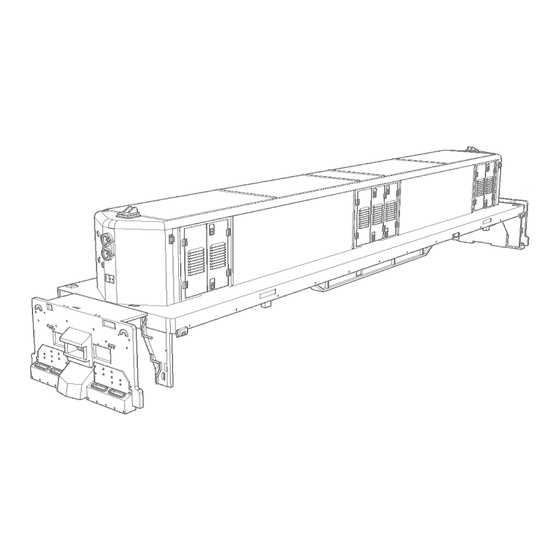
- Page 1 HO Scale GP9 SLUG Locomotive Kit Assembly Instructions This Model Represents GP9 SLUG, Class GY00d (CN# 215-232) and GY00e (CN# 233-241) The GP9 SLUG Locomotives Rebuilt 1986-1987 from GP9 Locomotives, Class GR-17, Originally Built 1955 To 1959...
-
Page 3: Parts List
Parts List Kit Parts Clear Parts GP9 SLUG Locomotive Body Headlight Frame MU Power connectors- small Wire Formed Parts MU Power connectors- large Grab Irons Air Filter Handrails- Sides (2-R, 2-L Side) Air Tank- Large Handrails- Ends (2-R, 2-L Side) - Page 4 Notes Prior to Assembly: • Use photos as a reference of specific road number you model, you can find plenty of them online • Grab a cup of coffee (important!) • While installing lightning do not to use bulbs (Not even 1.5v bulbs) •...
- Page 5 • This kit is designed to accept either Atlas or NWSL’s Stanton trucks. Perform a test run before assembly of detailed parts. • When adding weight please note according the NMRA’s standards, the total weight should be 5 ounces. Calculation according NMRA: Initial weight on 1 Oz plus 0.5 Oz per inch of car body length (Body length approximately- 8 inches)
- Page 6 Assembly Instructions • Remove and sand any remainings from printing process. while we have designed the model to have none visible from the outside of the model, some may be visible and interfere with the assembly. Next, 3D printed parts can be sanded easily with a #400 to #600 (wet / dry, preferred wet) sanding paper.
- Page 7 • Use #78 drill to drill holes for grab irons • Use #76 drills to drill holes for spare knuckle holder detail, please see Fig. 2 for drilling locations • Use #60 drill to drill hole for hand brake. • Cut 2 pieces of 0.1” (approximately 2.5 mm) from a 0.02” brass wire for the knuckle holder Sand Hatches •...
- Page 8 Etched Steps Assembly • Choose the type of step suited for the specific road number you model (diamond or rectangle mesh), Remove the steps from the fret, Bend short edge downwards in a 90 degree angle see fig. 3. • note the different sizes, the upper and middle steps are •...
- Page 9 Pilot/ Plow • observe prototype images and determined which (and if..) your model equipped with pilot. Rounded plow: sand plow to remove and remaining from printing process, also sand the detail from each side of the shell where you glue the plow front pilot with stepboard are assembled with the base with etched metal parts fig.
- Page 10 Installing Grab Irons and Spare Knuckle Holder • Insert the spare knuckle holder into place you have drilled in earlier step (Previously cut .02” brass, or other metal rod cut to 0.1” (approximately 2.5 mm) holes as shown in Fig. 7 and carefully glue in place, glue from the bottom side using ACC glue •...
- Page 11 Stanchion Assembly • Remove 4 of the shorter style stanchions (with support tabs) from the fret, bend over the small tabs on the bottom of the stanchion backwards as shown in Fig. 9, Then remove 2 more stanchions (longer type, with no tabs) and perform a fitting test as shown in Fig.
- Page 12 • Final assembly of stanchions and handrails • Bend over the stanchion at the upper tab to lock the • handrail in place. fig 12. • Inspect and assemble the handrails in place as shown in fig. 13...
- Page 13 • Side railings: please measure and cut the 4 climbing handrails to size (Brass wire), to fit at the middle of the first stanchion of each end. The first stanchion of each end should hold both the climbing railing and the long handrail. Cut to size at the other end as well.
- Page 14 • Glue the electrical components to both ends, as shown in fig. 15 • Find the brake wheel, glue in place as shown in Fig. 16.
- Page 15 Frame and underframe: Note: We have included 2 air tanks in the kit, one air tank designed to go with metal etched holder, the other small air tank have the holder attached to the tank as a single part, for easier installation, If you choose the second version you do not need the etched holder, obviously •...
- Page 16 • Follow Fig. 20 for complete frame and underframe detailing including air tank, air filters and other components. • Install a coupler housing (frame accpet easily Kadee® coupler pockets, but any other brand will work), perform a fitting test and trim if needed). Adding Headlight •...
- Page 17 • End pilot safety light: use a .01” fiber optic to illuminate the pilots safety lights using LED from the inside • Glue in place clear cast headlight, insert from the inside. Some modelers may want to perform this step after painting.
- Page 18 Notes: _________________________________________ _________________________________________ _________________________________________ _________________________________________ _________________________________________ _________________________________________ _________________________________________ _________________________________________ _________________________________________ _________________________________________ _________________________________________ _________________________________________ _________________________________________ _________________________________________ _________________________________________ _________________________________________ _________________________________________ _________________________________________ _________________________________________ _________________________________________ _________________________________________ _________________________________________ _________________________________________ _________________________________________ _________________________________________...
- Page 19 Notes _________________________________________ _________________________________________ _________________________________________ _________________________________________ _________________________________________ _________________________________________ _________________________________________ _________________________________________ _________________________________________ _________________________________________ _________________________________________ _________________________________________ _________________________________________ _________________________________________ _________________________________________ _________________________________________ _________________________________________ _________________________________________ _________________________________________ _________________________________________ _________________________________________ _________________________________________ _________________________________________ _________________________________________ _________________________________________ _________________________________________...
- Page 20 Feel free to contact us with any question and suggestions you might have at info@mapleleaftrains.com Visit us online at http://www.mapleleaftrains.com/ V1.0...
Need help?
Do you have a question about the GP9 SLUG and is the answer not in the manual?
Questions and answers