
Summary of Contents for Optronics PG11
- Page 1 PG11 / PGE11 Optical Gas Detection Operating Manual Website: Optronics-Technology.com...
- Page 2 Warnings It is important that the manual is carefully read in its entirety. The manual shall be read and understood by those having the responsibility for the Operation and Maintenance of the product. If the product is not used and maintained in accordance with the manufacturer’s instructions, the product may not perform as intended.
-
Page 3: Table Of Contents
5.1 Function test 5.1.1 PG11 function check with the “Gas Test kit” 5.1.2 PG11 Function check with the “Gas Free Test kit” 5.1.3 PG11 Function check using the “Gas nozzle” 5.1.4 PG11 Function check with the “Remote Gas Test kit”... - Page 4 7.3 Analog Safety output 7.4 HART® 7.4.1 HART® electrical connection 8 Warranty 9 Certifications and standards 9.1 Directives and standards 9.2 Approvals and Certificates 9.3 Marking 9.3.1 Certification 9.3.1.1 Ex db ib IIC T5 Gb 9.3.2 Vendor information 9.3.3 Serial number and year of manufacturing 9.4 Specific conditions of use 10 Troubleshooting 11 Accessories and Spare Parts...
-
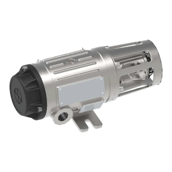
Page 5: Product Description And Detection Principle
1 Product Description and detection principle PG11 is an explosion proof rugged Optical Gas Detector for the detection of flammable gases and CO . The detector comes calibrated for life from the factory, and requires very little effort to install and maintain. -
Page 6: Technical Specifications
1.1 Technical Specifications Gas Detection by Dual band Optical absorption in target gases. Detection Solid-state Infrared SafeSource™ . Temperature compensated Optical Gas detection for rugged technology applications Detector configured from factory for one of the following gases with 100 %vol as maximum range: Methane ●... -
Page 7: Dimensions
1.2 Dimensions PG11 Mount Width Length height Document 022-80036-OM Revision R03 Page 7 of 48... -
Page 8: Dimensions Pge11
1.3 Dimensions PGE11 The PGE11 comes in three lengths with dimensions shown below. Mount Width Length height Document 022-80036-OM Revision R03 Page 8 of 48... -
Page 9: Detection Principle Of Pg11 And Pge11
1.4 Detection principle of PG11 and PGE11 PG11 is using an Optical Detection principle. The basic working principle is illustrated in the drawing below and consists of the following basic parts: A. Infrared light (2 - 6 µm region) is generated at the light source and directed at the B. -
Page 10: Safety And Warnings
2 Safety and Warnings PG11 PG11 Optical gas detector is certified for and intended for use in potentially hazardous areas. Install and use the gas detector in accordance with the appropriate local or national regulations. The gas detector shall be properly Earthed to protect against electrical shock and minimize electrical interference. -
Page 11: Installation
“3.4 Electrical connections and Earthing”. 3.2 Preparations and Positioning considerations PG11 is a point gas detector, and should be placed as close to a potential leaking point as possible. However, each installation is different from another, and detailed considerations must be done locally in order to get the best coverage for detection. -
Page 12: Mounting The Detector
3.3 Mounting the detector Below, PG11 is shown securely mounted with M8 mounting screws, nuts and washers. The PGE11 is mounted with the same solution. PGxx11 should be mounted with the longitudinal axis in the horizontal direction as illustrated below. -
Page 13: Pole Mounting
In the example below the detector is mounted in a C-bar structure. 3.3.1 Pole mounting Below is an illustration of the PG11 with the “Mount kit Pole” mounted to a pole with a diameter of about Ø60 mm or 3”. -
Page 14: Duct Or Pipe Mounting
3.3.2 Duct or pipe mounting If installed in a ventilation duct or pipe, it is recommended to use the “Duct flange kit” as shown in the illustration below. To get better gas coverage inside the duct it is recommended to use the PGE11 with the extended gas sensing section as shown below. The mounting is done by fixing the flange (A) to the installation. - Page 15 Duct testing. flange kit Installed with the Nozzle installed in the front PG11 of the PG11, and a flexible tube connected mounted in from the nozzle to the Duct flange. With the Duct flange Environment shield installed this solution...
-
Page 16: Electrical Connections And Earthing
3.4 Electrical connections and Earthing The PGxx11 chassis shall be connected to local Clean Earth. Use one of the two external Earthing points (M4x5) illustrated in point A left drawing below using an Earthing cable ring lug. The electrical terminals are located inside the rear lid in point B, opened by unscrewing the three screws fixing it. - Page 17 Table 2. Minimum voltage to PG11 shall be 18 VDC. Examples of cable and maximum length. Cable cross section 0.5 mm²...
-
Page 18: Booting Up The Gas Detector
3.4.2 Performing loop test The PG11 can perform a loop test through the HART of MODBUS interfaces. The loop test allows for the Operator to Manually set the analog signal output to a selected value for a limited time. Please consult the corresponding HART chapter of this Manual for instructions. -
Page 19: Environment Shield For
fire extinguishing systems. The optics of the PG11 is heated and the environmental shield will enhance the effect by keeping the heat more localized inside the sensing section of the PG11. The result is a more robust solution against thick mist and rapid temperature changes. -
Page 20: Sunshade
3.6 Sunshade The PG11 can be fitted with a screen or roof keeping it from being exposed to direct sunlight heating the detector up, or from snow, sand or similar that can accumulate on the detector. The sunshield is fitted as illustrated below. The sunshield is fixed with the same screws as the Detector. -
Page 21: Mosquito Net
Environment Shield for a combined splash and insect protection. 4 Commissioning the Gas Detector Below is the recommended procedure for commissioning the detector PG11: 1. Turn on power to the Gas Detector. The Detector will run self-diagnostics and warm up as described in section “3.4.1 Booting up the Gas Detector”... -
Page 22: Operation
Therefore precautions have to be taken when testing a detector to get valid results. For example using a 50 %LEL test gas and injecting it at 2 liters/min into a PG11 fitted with Environment Shield using the “Gas test kit”, can result in a gas reading as low as 20 %LEL if there is windy conditions. -
Page 23: Function Check With The "Gas Test Kit
5.1.1 PG11 function check with the “Gas Test kit” Using the PG11 Gas Test kit allows for quickly verifying the functionality of the Detector without having to remove the Environment shield if fitted. The Gas Test kit has an opening in the front between the gas nozzles that allows for the Operator to see the indicator showing the status of the Detector. -
Page 24: Function Check With The "Gas Free Test Kit
5.1.2 PG11 Function check with the “Gas Free Test kit” Using the Gas Test kit Gas Free, the Safety Function of the Gas Detector can be verified without the need of a bottle of test gas. The Gas Free Test kit comes in several types rated for different gases and with specified gas values. -
Page 25: Function Check Using The "Gas Nozzle
● Flexible gas hose Procedure: 1. If PG11 is not already fitted with a Gas nozzle, please fit this to PG11 as illustrated below at point A. 2. Verify that PG11 is fitted with an Environment Shield. Not having an Environment Shield will make the gas dilute too quickly giving low gas reading, especially in windy conditions. -
Page 26: Function Check With The "Remote Gas Test Kit
flow from the Gas test box and into the Gas Detector through the Gas nozzle. Requirements: ● PG11 should be fitted with the Environment Shield especially if there is any wind. ● Gas cylinder with same type of gas as Detector is rated to detect ○... -
Page 27: Pge11 Short And Medium Function Check
5.1.5 PGE11 short and medium Function check For the Function test of the PGE11 short and medium use the PGE11 Gas Test kit as described in the procedure below. The Function test is not taking into account variations in ambient pressure, wind or other factors so it is not expected to precisely verify the accuracy of the detector. -
Page 28: Perform A Check Of The Gas Detector Accuracy
5.2 Perform a check of the Gas Detector accuracy The PG11 and PGE11 have been calibrated for life at the Factory and do not require to be recalibrated. At the Factory great care has been taken to take into account environmental effects such as gas concentration, the temperature of the gas, ambient pressure and humidity... -
Page 29: Maintenance
6 Maintenance Very little Maintenance is required for PG11. The detector does not have any internal functions that require regular monitoring or maintenance. Regular maintenance consists only of cleaning the optics and inspecting the detector exterior for damage. Any damage to the internal of the detector is handled by the detector Self Diagnosis described in a separate chapter. -
Page 30: Keeping A Stable Zeroing Of The Detector
6.3 Keeping a stable Zeroing of the Detector 6.3.1 The OptoBAS™ function The OptoBAS™ function of PG11 is keeping the Maintenance requirements of the detector to a minimum by taking away the need to do manual zeroing of the detector. This will make sure the detector will show zero gas value when there is no gas present. -
Page 31: Self Diagnostics
6.4 Self Diagnostics All Safety critical electronic components are monitored and stored in the Diagnostics log if outside specification. In addition vibration, temperature and optical signals are analyzed and stored in the Diagnostics log. The Diagnostics log is downloaded at the vendor during any Service or inspection of the Detector. -
Page 32: The Blocking Kit - Protection During Site Maintenance
6.5 The Blocking kit - Protection during site Maintenance Site Maintenance such as sand blasting and painting might damage the detector. To protect the Detector during such work it is recommended to use the Blocking kit accessory. The Blocking kit will fit into the Detector as illustrated below, protecting both the Optics and Detector from pain, sandblasting and dirt. -
Page 33: Signal Outputs
7 Signal outputs 7.1 Detector status flags In the table below are the status flags for the PGxx11. Not all status flags below will have any impact on the 0-20 mA Safety output. All statuses will be available through HART or the independent MODBUS digital output: ●... -
Page 34: Light Indicator
Arctic detector is warming up electronics at extreme temperatures before booting up the rest of the electronics. 7.2 Light indicator The PG11 has a built in multicolor light indicator with the following settings: Status type Indicator Description and typical applications... -
Page 35: Analog Safety Output
7.3 Analog Safety output All analogue output values in the table below have a ± 0.25 mA range applied, and are in accordance with recommendations by NAMUR NE043 (2003) and NE107 (2017). Table 4. Description of the Detector analog output. Status type Output Default... -
Page 36: Hart
7.4 HART® PG11 has a HART digital protocol superimposed on the current loop output. The HART® commands are described in the document PGxx11 HART interface instruction. 7.4.1 HART® electrical connection A HART Master requires a minimum loop resistance of 250ohm for communication. -
Page 37: Warranty
● 6 (six) years warranty for manufacturing defects ● 15 (fifteen) years warranty for IR source PG11 warrants for normal use within gas detection, in accordance with the technical manual. Contact your supplier for further instructions on warranty and claims procedures. -
Page 38: Marking
9.3 Marking 9.3.1 Certification 9.3.1.1 Ex db ib IIC T5 Gb Ex db eb ib IIC T5 Gb 9.3.2 Vendor information 9.3.3 Serial number and year of manufacturing Document 022-80036-OM Revision R03 Page 38 of 48... -
Page 39: Specific Conditions Of Use
9.4 Specific conditions of use ● Flameproof joints are not intended to be repaired. ● The user must always ensure that the measuring function complies with the requirements from the relevant harmonized standards which provide guidance on the performance of Gas detection equipment and Safety devices. ●... -
Page 40: Troubleshooting
10 Troubleshooting Do not return the Gas detector to the supplier for repair if the procedure below has not been performed. Below is the Fault finder diagram. Before performing the Fault finder it is recommended to check the Detector Error code by connecting with HART of MODBUS interfaces and look up the recommended fix in table 5. - Page 41 Table 5. Overview of possible issues and suggestions for solutions. Error codes can be found through the HART or MODBUS interfaces. Please consult the corresponding chapter for instructions. Issue type Issue description Suggested cause/solution Signal Unstable detector reading Verify that the detector has sufficient local Earthing.
-
Page 42: Accessories And Spare Parts
11 Accessories and Spare Parts Below is an overview of accessories and spare parts for the PG11. Use the ordering number to refer to these parts when in contact with the Supplier. Ordering Part Description number ACC-ENV-STD Environment Shield To prevent water and other liquids from spraying... - Page 43 ACC-MB-KIT Maintenance Blocking Kit to block the gas detector and prevent damage during for example sandblasting or paint work. The kit will be very visible showing that the detector is blocked. The kit can be set to force the detector into FAULT as long as the kit is bocking.
-
Page 44: Product Coding And Ordering Information
Commercial codes for products are made by various main elements that each are separated with a hyphen in the following way: 1. Product family, alphanumeric text string with variable length (e.g. "PG11") 2. Gas type, two letters (each combination represents one unique, several different or one unique with immunity to one or several) 3. - Page 45 PG11, Methane, 0-100 %Vol, ATEX/IECEx, Source PG11-AB-03-AA-0000 PG11, Propane, 0-100 %LEL, ATEX/IECEx, Source PG11-AW-03-AA-0000 PG11, Ethylene, 0-100 %LEL, ATEX/IECEx, Source PG11-BA-21-AA-0000 PG11, Carbon Dioxide, 0-1 %Vol, ATEX/IECEx, Source PG11-BA-25-AA-0000 PG11, Carbon Dioxide, 0-10 %Vol, ATEX/IECEx, Source PG11-BA-27-AA-0000 PG11, Carbon Dioxide, 0-25 %Vol, ATEX/IECEx, Source PG11-BD-29-AA-0000...
-
Page 46: The Optocom™ Module
In the below illustration To install an OptoCom™ module the rear lid of PG11 is removed. In the illustration below the OptoCom™ module B is slotted into terminal A. The original lid is replaced by the OptoCom™... -
Page 47: Abbreviations
14 Abbreviations ATEX Atmosphere Explosives Electrochemical detection technology. Electromagnetic Compatibility Full Scale. Full gas range for the detector, for example 0 - 100 %LEL or 0 - 100 %vol. HART Highway Addressable Remote Transducer communication protocol Infrared light. IECEx International Electrotechnical Commission Explosion Lower Explosive Limit MODBUS Master-slave messaging structure... -
Page 48: Safety Manual
15 Safety Manual This is a separate document: 022-80043-SM PGxx11 Safety Manual 16 Support and Contact details If there are any issues with the detector, please check the Troubleshooting chapter. Do not return the Gas detector to the Supplier for repair if it has not been troubleshooted according to the procedure in the troubleshooting chapter.
Need help?
Do you have a question about the PG11 and is the answer not in the manual?
Questions and answers