
Related Manuals for Touch-plate SLR-UD-RT

Summary of Contents for Touch-plate SLR-UD-RT
- Page 1 SLR-UD-RT Leading Edge Controller User Manual May, 2020 TouchPlate LED Lighting and Controls, Inc - Please read this manual carefully before using the product SLR-UD-RT series User Manual V03.1 www.touchplate.com...
-
Page 2: Table Of Contents
6.2 Fade Time Set ..................................7 6.3 Threshold Set ..................................7 7 System Setting ....................................8 7.1 Factory Reset ..................................8 7.2 Backlight ................................... 8 8 System Info ....................................9 9 Wiring Diagram ..................................10 SLR-UD-RT series User Manual V03.1 www.touchplate.com... -
Page 3: Product Features
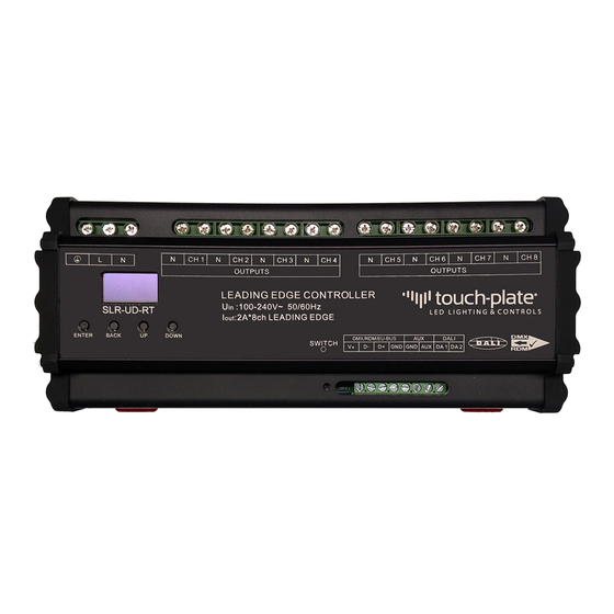
2 Technical Parameters Item Parameters Input control signal DMX512(1990)/RDM,DALI Input voltage 100-240VAC 50/60Hz Max output current 2A*8ch 8.76”x3.68”x2.49” (LxWxH) fits standard 35mm din rail Equipment size G.W. 2.25 lbs Operational temperature 0-125°F 2.1 Dimensions (inch) SLR-UD-RT series User Manual V03.1 www.touchplate.com... -
Page 4: Function Of The Product
Move the menu cursor up / Increase the value of the option Note: Long press "UP" to increase the value rapidly Move the menu cursor down / Decrease the value of the option DOWN Note: Long press "DOWN" to decrease the value rapidly SLR-UD-RT series User Manual V03.1 www.touchplate.com... -
Page 5: Control Mode
DMX address for each channel (acceptable range: 1-511). Each channel is independent of one another. The channels can be the same or different, and can be continuous or discontinuous. You can control a group by setting the same address for all the channels. Figure 4 Figure 5 SLR-UD-RT series User Manual V03.1 www.touchplate.com... -
Page 6: Dali Mode
You can choose the output type for each channel. There are two output types: SW and LPC. a) SW: Switching, On/Off b) LPC: Dimming leading edge drivers or lighting loads Figure 10 Figure 11 SLR-UD-RT series User Manual V03.1 www.touchplate.com... -
Page 7: Fade Time Set
> 0, the output channel is set to the threshold setting. When the received brightness is > the threshold setting, the output channel is the received brightness value. Figure 14 Figure 15 SLR-UD-RT series User Manual V03.1 www.touchplate.com... -
Page 8: System Setting
60 seconds of no activity. Press any key to end the sleep mode and wake the screen up. When the backlight is set to "No" the display will remain on and at the last used menu. Figure 18 Figure 19 SLR-UD-RT series User Manual V03.1 www.touchplate.com... -
Page 9: System Info
Page 4 (Figure 26) Line 1 System Info Line 3 Solare Universal Line 4 Firmware creation date Line 5 Firmware creation time Line 6 TouchPlate, Inc. Figure 20 Figure 21 Figure 22 Figure 23 Figure 24 SLR-UD-RT series User Manual V03.1 www.touchplate.com... -
Page 10: Wiring Diagram
9 Wiring Diagram SLR-UD-RT series User Manual V03.1 www.touchplate.com...
Need help?
Do you have a question about the SLR-UD-RT and is the answer not in the manual?
Questions and answers