Table of Contents
Advertisement
Quick Links
Advertisement
Table of Contents

Related Manuals for Nastec 3600-24


Summary of Contents for Nastec 3600-24
- Page 1 3.6kW/6kW OFF GRID SOLAR INVERTER User Manual 202401 Ver:1.0 4257-0958...
- Page 2 Copyright Statement The copyright of the Manual is owned by the manufacturer. Please keep the Manual properly and strictly follow all safety and operating instructions in the Manual. Do not operate the inverter before reading the Manual.
-
Page 3: Table Of Contents
User Manual User Manual 8.3 Collector Status Safety Introduction 8.4 Handling of Abnormal Conditions 1.1 Proper Manual Keeping 8.5 Operation Method of the Reset Button 1.2 Requirements for Operators SOLARMAN Smart APP 1.3 Warning Signs 1.4 Setting of Safety Warning Signs 9.1 Registration 1.5 Measuring Equipment 9.2 Create a Plant... -
Page 4: Safety Introduction
User Manual User Manual Safety Introduction 1.4 Setting of Safety Warning Signs During guidance, maintenance, and repair processes, please follow the 1.1 Proper Manual Keeping instructions below to prevent misuse by non-professionals or accidents: The Manual contains vital information regarding equipment operation. Please ●... -
Page 5: Introduction
User Manual User Manual Introduction 1.7.8 During installation or maintenance, take care to prevent tools from falling, which could lead to battery short circuits. This is a multifunctional integrated inverter that combines the functions of an 1.7.9 Adopt PV junction boxes with surge protection. Otherwise, damage to the inverter, solar charger, and battery charger, ensuring uninterrupted power inverter may occur when the PV modules are struck by lightning. -
Page 6: Characteristics
User Manual User Manual Characteristics System Infrastructure With advanced topology architecture, the battery inverter efficiency can The diagram below illustrates the basic application of the device, requiring the reach up to 93.5%. following equipment to have a complete operating system: Generator or utility power Pure sine wave inverter PV modules... -
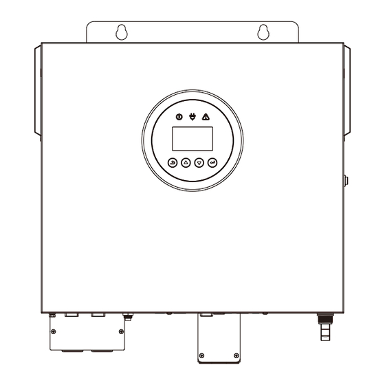
Page 7: Product Overview
User Manual User Manual Product Overview Installation 11 12 The Manual outlines the basic steps for installing and setting up the inverter. Be careful when unpacking to prevent damage to the components. 6.1 Unpacking and Inspection Before installation, please inspect the equipment to ensure there is no damage to the packaging. -
Page 8: Installation Preparation
Note! To ensure safe operation and compliance, a separate DC overcurrent protector or disconnecting device between the battery and inverter is required. ( 2) Based on cable sizes, prepare two battery wires for the 3600-24 In some applications, installing circuit breakers may not be essential, but model, one battery wires for the 3600-48 model, and one or two battery overcurrent protection devices are still recommended. -
Page 9: Ac Input/Output Connection
Wire Specifications for Standard Configuration of 3.6K-6K Split Unit Model 3600-24 3600-48 6000-48 AC input current/A 15.7 15.7 3600-24 (using 2*1AWG battery wires) 3600-48 (using 2AWG battery wires) Cross-sectional area of the wire 3mm ² 3mm ² 5mm ² 6000-48 (using 0AWG/2*2AWG battery wires) Wire diameter... -
Page 10: Pv Connection
To prevent this kind of damage, please check if the air INVERTER MODEL 3600-24 3600-48 6000-48 conditioner manufacturer has provided a time-delay function before... -
Page 11: Communication Connection
User Manual User Manual 6.6 Communication Connection Connect all communication lines according to the following diagram. Dry contact port: Unit Status Condition NC C NO NC & C NO & C Unit is off and no output is powered. Open Power Off... -
Page 12: Operation
User Manual User Manual Operation 7.2 Operation and Display Panel 7.1 Power On/Off The LCD operation panel shown in the diagram below consists of O n c e t h e d e v i c e i s c o r r e c t l y f o u r t o u c h - s e n s i t i v e f u n c t i o n installed and the battery is well keys, an LCD display, and LED... -
Page 13: Display
User Manual User Manual 7.4 Display 7.4.1 Main Interface Display SETUP 1. Setting interface of AC input range GRID DATA 1:AC IP RANGE OUTPUT 2.Output VOLG: 0.0V Power grid port VOLG: 229.2V Output display 2:OUTPUT 3. Setting interface of output source priority CUR:... - Page 14 User Manual User Manual (4_1) M AX CHG (1_1) SBU CHG (1_2) SBU DSCHG (4_2) MAX AC CHG MAX AC CHG MAX CHG Setting interface Setting interface Setting interface Setting interface SBU CHG SBU DSCHG CURRENT: 30 A CURRENT: 30 A of SBU discharging of SBU charging of maximum AC...
- Page 15 User Manual User Manual (7_1) PAR 7.4.2.7 Basic settings interface PAR ADDR 1.Parallel address Interface Description 1:PAR ADDR 2.Parallel redundancy Setting interface 2:PAR TTL NUM number of parallel address BASIC SET 1. Language setting interface 3:PAR RED NUM 3. Idle shutdown 1:LANGUAGE 2.
-
Page 16: Settings
User Manual User Manual 7.5 Settings " 7.5.1 Return Key" ( 3) Setting interface of charging source priority Pressing the return key on the main display interface allows entry into the Description Interface settings menu interface. Pressing the return key on the settings menu SNU (default): Solar energy and utility will interface allows returning to the main display interface. - Page 17 Description Description Interface Interface For the 3600-24 model and 6000-48 model, the SBU charging voltage can be set. For the 3600- SBU CHG default charging current is 30A, with the ability to 24 model, the default voltage is 23V and the MAX CHG VLTG:...
- Page 18 User Manual User Manual (17) Buzzer setting ( 22) SBU charging voltage setting Description Description Interface Interface GENERATOR BUZZER Compatible generator (DISABLE by default), which 1:DISABLE 1:DISABLE 2:ENABLE 2:ENABLE can be set to DISABLE or ENABLE. ( 23) Clear record setting (18) Record interface Description Interface...
- Page 19 User Manual User Manual ( 27) Parallel address setting (33) Electricity for the month Description Interface Description Interface PAR ADDR E-MONTH PV represents the monthly PV power generation. Able to set parallel address, with the default ID PV: 2KWH LOAD represents the monthly power consumption as 1.
-
Page 20: Wireless Router Operation Guide
User Manual User Manual 8.3 Collector Status Wireless Router Operation Guide 8.1 App Download Indicator Description Status description (All indicators are single green Step: Scan the QR code to download the APP. Light Off: unable to connect to the router. 1s On/1s Off... -
Page 21: Operation Method Of The Reset Button
User Manual User Manual 1. Loose or 1. Normal Abnormal READY abnormal connection between power READY Fault connection the collector and Fault causes Solutions between the supply description router, but abnormal collector and connection between inverter the collector and 2. Insufficient Abnormal 1. -
Page 22: Registration
User Manual User Manual 9.3 Add a Collector Method 1: Manually enter the collector SN code. 9.1 Registration Method 2: Tap on the icon on the right to scan and enter the SN code. You can find the SN code on the outer package and casing of the collector. To register your information on SOLARMAN Smart, please tap on "Register"... - Page 23 User Manual User Manual Step 3: Automatic configuration Please wait for some time to complete the configuration. Then proceed Please make sure that your to the next page. Tap on "Done" and check the plant data. (Usually, the phone is connected to the data will be updated within 10 minutes).
-
Page 24: Alarm And Fault Codes
User Manual User Manual Alarm and Fault Codes English Description Code 10.1 Alarm Codes Bms_VersionErr Code English Description Bms_UpdateFail Grid Volt Low CT Converse Grid Volt High Cl0ck fail Grid Frequency Low PV off Grid Frequency High System Reset Solar Loss 10.2 Fault Codes Bat Loss Bat Under Volt... -
Page 25: Fault Diagnosis And Handling
User Manual User Manual Fault Diagnosis and Handling Code English Description The inverter is user-friendly for maintenance. When you encounter the following problems, please refer to the following solutions. If the problem persists, please contact the local distributor. The table below lists some basic problems that may occur in actual operation and their corresponding basic solutions. - Page 26 User Manual User Manual Type Code Solutions Type Code Solutions Abnormal (1) Check if the input mode is correct; (1) Please contact the distributor. inverter output (2) Disconnect the PV input, restart the machine and (1) Restart the inverter and observe if the machine can observe if it can return to normal;...
- Page 27 User Manual User Manual Type Code Solutions Model 3600-24 3600-48 6000-48 (1) Check if the PV string is directly or indirectly grounded; Leakage (2) Check if there is leakage current in the peripheral PV terminal current error facilities of the machine;...
-
Page 28: Routine Maintenance
User Manual User Manual Routine Maintenance 5%~95% (without condensation) Relative humidity 13.1 Inspection Plan for Cables, Equipment and Terminals 13.1 Inspection Plan for Cables, Equipment and Terminals LCD/APP Display (Every six months) RS232/USB/Dry Contact; Communication interface Inspect if wire connections are loose. Optional:RS485/CAN/WIFI Inspect if the cables are aged/damaged. -
Page 29: Quality Commitment
User Manual User Manual Quality Commitment Step 1: First turn off all power sources of the machine and put it in a shutdown state. The manufacturer is responsible for the damage that occurs during normal use under the required environment during the warranty period. For faults during the warranty period, the manufacturer will provide free spare parts to the agent/dealer. -
Page 30: Limitation Of Liability
User Manual Limitation of Liability No direct or indirect liability will be assumed for product damage or property loss caused by the following circumstances: Product modification, design alteration, or component replacement without manufacturer's authorization; Change and repair of seals, or removal of serial numbers or by non- manufacturer technicians;...
Need help?
Do you have a question about the 3600-24 and is the answer not in the manual?
Questions and answers