
Subscribe to Our Youtube Channel
Summary of Contents for Dobot VX500
- Page 1 Dobot VX500 Smart Camera User Guide Issue: V1.2 Date: 2024-02-28 Shenzhen Yuejiang Technology Co., Ltd. | China...
- Page 2 AS IS, which may have flaws, errors or faults. Dobot makes no warranties of any kind, express or implied, including but not limited to, merchantability, satisfaction of quality, fitness for a particular purpose and non-infringement of third party rights.
-
Page 3: Preface
VX500 SmartCamera firmware V3.1.0 240221 and above DobotCalibrate program V1.0.6 and above NOTICE The schemes created by the older version of VX500 plugin are not available in the current version. You need to create new schemes. Revision history Date Version... -
Page 4: Table Of Contents
Dobot VX500 Smart Camera User Guide Contents Preface ........................... ii 1. Product Introduction ....................1 2. Software/Hardware Installation and Connection ..........3 2.1 Hardware installation and connection ................3 2.2 Software installation and connection ................4 3. Software Main Interface ..................7 4. - Page 5 Dobot VX500 Smart Camera User Guide 6.4 Calibration file management ................... 44 6.5 Coordinate system management ..................45 7. Vision tool ....................... 47 7.1 Positioning tool ....................... 47 7.1.1 2.5D positioning ....................47 7.1.2 2D positioning ....................47 7.2 Recognition tool ......................47 7.2.1...
-
Page 6: Product Introduction
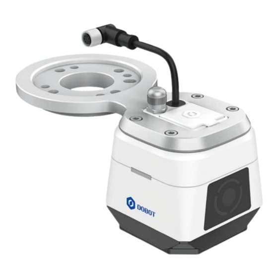
Dobot VX500 Smart Camera User Guide 1. Product Introduction Dobot VX500 smart camera adapts to Dobot CRA series robots (except CR20A), which is plug-and-play. With an embedded high-performance vision system, the smart camera helps the robot identify directions, position accurately and execute vision schemes to realize Dobot universal vision solutions. - Page 7 Dobot VX500 Smart Camera User Guide Definition Definition 485B Digital output 2 Digital input 2 Digital output 1 Digital input 1 Aviation socket: When the end tool needs to communicate with the robot arm via an aviation plug, you can connect the aviation plug to this socket for communicating with the robot arm.
-
Page 8: Software/Hardware Installation And Connection
CR20A). 2.1 Hardware installation and connection 1. Connect the aviation plug of the VX500 smart camera to the aviation socket on the end of the robot arm. 2. Install the connecting flange to the end of the robot arm using four M6 screws. -
Page 9: Software Installation And Connection
NOTE Only Chinese and English are available for the current version of the VX500 plugin. 5. Open the VX500 plugin, and wait for the plugin to search for the smart camera connected to the computer via the network cable. NOTE Please turn off the firewall on your computer before connecting to the ... - Page 10 Dobot VX500 Smart Camera User Guide the same network segment. 7. Click Connect, and the plugin starts to connect to the smart camera. After connection, you will enter the Camera settings page. You can click Disconnect to disconnect from the current camera and search for the camera again.
- Page 11 Dobot VX500 Smart Camera User Guide NOTICE The path to the upgrade file only supports English and the current language of the operating system. During the upgrade, do not disconnect the camera or cut off the power. If the version of the upgrade target is inconsistent with the first two digits of ...
-
Page 12: Software Main Interface
Dobot VX500 Smart Camera User Guide 3. Software Main Interface The left side of the page displays the camera image. After connection, the image area displays the last image taken by the camera. You can click Take photo on the top right corner of the image to control the camera to ... -
Page 13: Camera Settings And Parameters
Dobot VX500 Smart Camera User Guide 4. Camera Settings and Parameters 4.1 Camera settings 4.1.1 Camera settings Device alias is editable. You can set aliases to distinguish different camera devices. IP/Gateway/Subnet mask shows the current network configuration of the camera. -
Page 14: D Positioning Code
2.5D positioning code Select the actual size of the 2.5D positioning code (select based on what you actually use). The standard product is a VX500 shipping accessory, and the size of the standard product is the overall size including the outer frame of the positioning code. -
Page 15: Camera Parameters
Dobot VX500 Smart Camera User Guide NOTE If you want to print the 2.5D positioning code by yourself, you can download the drawing from Dobot website. The size of the positioning code is set globally, and different sizes of ... -
Page 16: Photography Trigger Mode
Dobot VX500 Smart Camera User Guide 4.2.1 Photography trigger mode The smart camera supports the following photography triggering modes. Regardless of the trigger mode, the photography that triggers automatically when you set the camera parameters is always effective. Auto photography: The camera automatically takes photos at regular intervals (non-real-time ... -
Page 17: Setting Light Source
Dobot VX500 Smart Camera User Guide Manual settings Brightness settings Click One-click settings to automatically adjust the brightness of the camera. If One-click settings does not meet your requirements, you can manually adjust the brightness of the camera image by modifying the exposure time. -
Page 18: Setting Gamma
Dobot VX500 Smart Camera User Guide Duration: Set the light-up duration of each light bead. It can be set only when the Light source control is All, the set parameters are also valid for the light beads turned on in the Custom mode. -
Page 19: Scheme
A scheme is a collection of tools, and multiple tools can be set in a scheme. There is an empty scheme without any tools and configurations that comes with the VX500 smart camera, you need to create your own scheme according your needs. - Page 20 Dobot VX500 Smart Camera User Guide You can click Delete to delete the tool. You can click Copy to make a copy of the same tool. Up to 40 tools can be included in a scheme, and each tool has its own limit. For example, the 2.5D positioning and code recognition module only allow one respectively.
-
Page 21: Running Scheme
Dobot VX500 Smart Camera User Guide 5.2 Running scheme Click Run once to run the current scheme one time (take a photo and recognize it one time), and display the running results. The corner mark on the right of the scheme name represents the real-time running ◦... -
Page 22: Managing Scheme
Dobot VX500 Smart Camera User Guide The count of the running results of the current scheme is displayed under the scheme ◦ name. You can click to reset the count to zero. The tool result area displays the running results of each tool in the current scheme. - Page 23 Dobot VX500 Smart Camera User Guide Select a scheme and click Set as current scheme, you can set the selected scheme as the current scheme. Click to delete the scheme. The current scheme cannot be deleted. Issue V1.2 (2024-02-28) User Guide Copyright ©...
-
Page 24: Calibration And Coordinates
6.1.1 2.5D vision scheme 2.5D positioning is a self-developed algorithm by Dobot, which can solve the problem of inaccurate positioning caused by spatial height conversion (such as uneven ground, tilting, etc.), while conventional 2D positioning cannot solve such problem. For example, if the robot arm is... -
Page 25: D Calibration And Coordinate System
Dobot VX500 Smart Camera User Guide photo point in the actual application scene is different from the calibrated photo point. 2) Create 2D coordinate system: Create a 2D coordinate system by recognizing the image specified by the user. 3) Add tool: Add 2D positioning tool and output settings to the scheme. - Page 26 Dobot VX500 Smart Camera User Guide NOTE To ensure accuracy, when performing 2.5D calibration, you need to: Set the User coordinate system and Tool coordinate system to 0 in Jog panel. Keep the joint angle of J3 positive when setting the calibration points.
- Page 27 Dobot VX500 Smart Camera User Guide Move the robot arm to align the center of the end flange with the center of the calibration board (You can install a calibration needle at the end of the robot arm for alignment, with no height requirement, and try to keep the error less than 10mm).
- Page 28 Dobot VX500 Smart Camera User Guide ③ Collect calibration point The robot has automatically generated 25 points. Please ensure there are no obstacles within the motion range of the robot arm. Click Start collecting, and the robot will automatically move to the points and collect the images.
- Page 29 Dobot VX500 Smart Camera User Guide letters, numbers and underscores) and save. When the calibration result is Good, you can view the error data and decide whether to recalibrate or save the calibration file directly according to the site requirement for calibration accuracy.
- Page 30 Dobot VX500 Smart Camera User Guide Adjust the posture of the robot arm to keep the camera lens parallel to the 2.5D calibration board, and ensure that the calibration board is located in the center of the image vision field and accounts for 70% of the vision field. It is recommended that the camera lens be at a height of 250mm –...
-
Page 31: Common Causes Of Calibration Failure
Dobot VX500 Smart Camera User Guide When the calibration result is Excellent, enter the file name (can only contain English letters, numbers and underscores) and save. When the calibration result is Good, you can view the error data and decide whether to ... - Page 32 Dobot VX500 Smart Camera User Guide Before creating a coordinate system, you need to select a saved 2.5 D calibration file. Then click Create coordinate system. Move to photo point ① Fix the 2.5D positioning code on a flat surface. Move the robot arm to make the camera lens parallel to the 2.5D positioning code, and make the 2.5D positioning code in the center of the image...
-
Page 33: Calibration And Coordinate System
Dobot VX500 Smart Camera User Guide After you save the coordinate system, the interface returns to the Calibration and Coordinates page and displays the created coordinate system and corresponding calibration board. Clicking the calibration board diagram can view a larger image. - Page 34 Dobot VX500 Smart Camera User Guide NOTE To ensure accuracy, when performing 2D calibration, you need to: Set the user coordinate system to 0 in Jog panel. Keep the joint angle of J3 positive when setting the calibration points. 2D automatic calibration For 2D automatic calibration, the robot arm automatically generates 14 calibration points after you set the photo point, template and offset.
- Page 35 Dobot VX500 Smart Camera User Guide Overwrite the current point to “2D photo point”. NOTE As the 2D calibration only supports taking photos at fixed point, when using the calibration file, make sure that the robot arm is at the same point every time you take a photo.
- Page 36 Dobot VX500 Smart Camera User Guide Make sure the calibration board is in the center of the screen. Click Edit on the right of Issue V1.2 (2024-02-28) User Guide Copyright © Yuejiang Technology Co., Ltd.
- Page 37 Dobot VX500 Smart Camera User Guide Template area, frame the circle in the center of the calibration board using the rectangle tool. Then click on the right of Template matching point, and click the intersection of the cross in the center of the circle.
- Page 38 Dobot VX500 Smart Camera User Guide Set the offset of the automatically generated points. The plugin will automatically generate 14 points centered on the photo point based on the offset you set. The first nine points are translation points (translation along the X and Y axes), the last five points are rotation points (rotation along the Rz axis only, the distribution will be different depending on the angles).
- Page 39 Dobot VX500 Smart Camera User Guide When the calibration result is Excellent, enter the file name (can only contain English letters, numbers and underscores) and save. When the calibration result is Good, you can view the error data and decide whether to ...
- Page 40 Dobot VX500 Smart Camera User Guide Adjust photo point Please create a new project in Application (Blockly/Script programming) and create a new point (recommended to set the alias as “2D photo point”) in Points page. Manually modify RX to 180°/-180° and RY to 0°, and move to that point to keep the camera lens parallel to the work plane (e.g., the plane where the detected object is located in the actual...
- Page 41 Dobot VX500 Smart Camera User Guide Place the 2D calibration board on the work plane, making sure that the calibration board is in the center of the image vision field (remove the coverings if the eight circles were covered in previous 2D automatic calibration).
- Page 42 Dobot VX500 Smart Camera User Guide Issue V1.2 (2024-02-28) User Guide Copyright © Yuejiang Technology Co., Ltd.
- Page 43 Dobot VX500 Smart Camera User Guide Make sure the calibration board is in the center of the screen. Click on the right of Template area, frame any circle on the calibration board using the rectangle tool. Then click on the right of Template matching point, and click the intersection of the cross in the center of the circle.
- Page 44 Dobot VX500 Smart Camera User Guide Draw a rectangle in the base image on the left, frame a single circle, and click Collect. The system will recognize the calibration points based on the template. Repeat the steps above to complete the collection of 9 calibration points.
-
Page 45: Common Causes Of Calibration Failure
Dobot VX500 Smart Camera User Guide When the calibration result is Excellent, enter the file name (can only contain English letters, numbers and underscores) and save. When the calibration result is Good, you can view the error data and decide whether to ... - Page 46 Dobot VX500 Smart Camera User Guide Create coordinate system. To establish a 2D coordinate system, you need to select the scheme to which the coordinate system belongs. You can use the 2D positioning tool only if the scheme is associated with a 2D coordinate system.
- Page 47 Dobot VX500 Smart Camera User Guide photo point. NOTE Set the user coordinate system to 0 in Jog panel before taking a photo. Set template ② Make sure the calibration board is in the center of the screen. Click Edit on the right of Template area, frame the circle in the center of the calibration board using the rectangle tool.
- Page 48 Dobot VX500 Smart Camera User Guide click on the right of Template matching point, and click the intersection of the cross in the center of the circle. For more details on advanced settings of templates, refer to the instructions for Template matching.
-
Page 49: Calibration File Management
Dobot VX500 Smart Camera User Guide After successful recognition, select the name of the user coordinate system that you want the template to correspond to, and click Finish to save it. If the coordinate system fails to be recognized, check whether the image is clear and whether the template has been set. -
Page 50: Coordinate System Management
Dobot VX500 Smart Camera User Guide 6.5 Coordinate system management When the calibration file is a 2.5D calibration file, you will see Update in the Operate column of the created coordinate system, which is used to update the 2.5D coordinate system directly from this page. - Page 51 Dobot VX500 Smart Camera User Guide NOTICE Do not modify or clear the camera coordinate system (Cam_User) in the User coordinate system page of DobotStudio Pro, otherwise it may cause the camera project to run abnormally. Issue V1.2 (2024-02-28) User Guide...
-
Page 52: Vision Tool
Dobot VX500 Smart Camera User Guide 7. Vision tool 7.1 Positioning tool 7.1.1 2.5D positioning When you select a 2.5D calibration file and create a 2.5D coordinate system, you can update the 2.5D user coordinate system using this tool together with programming. -
Page 53: Character Recognition
Dobot VX500 Smart Camera User Guide 1. Set the detection area according to your actual need, with full screen by default. You can also select the detection area with the rectangle tool. 2. Set the code type to be recognized (can select multiple) and the maximum number of codes to be recognized each time (range: 1 –... -
Page 54: Measuring Tool
Dobot VX500 Smart Camera User Guide Set the detection area according to your actual need, with full screen by default. You can also select the detection area with the rectangle tool. Set the basis for judging the tool result. When the basis is set to Character score, you need to set the minimum score. If ... -
Page 55: Diameter Measurement
Dobot VX500 Smart Camera User Guide Draw two edges of which the width is to be measured within the detection area through If there is a part of the detection area that needs to be shielded, you can click Edit and draw the shielded area using the polygon tool. - Page 56 Dobot VX500 Smart Camera User Guide 1. Use the tool , click the center of the circle to be measured to generate a fixed-size circular detection area. You can adjust the size by yourself. If the clicked area is too close to the edge of the image, the circular detection area will exceed the image area and the drawing will fail.
-
Page 57: Grayscale Area
Dobot VX500 Smart Camera User Guide 4. Set the OK range of the tool result. If the measured pixel diameter is within the range, it is OK, otherwise it is NG. 5. If you find that the results of circle detection are not satisfactory after running, you can set the extended parameters. -
Page 58: Tool Existence
Dobot VX500 Smart Camera User Guide Set the detection area according to your actual need, with full screen by default. You can also select the detection area through the rectangle/circle/polygon tool. If there is a part of the detection area that needs to be shielded, you can click Edit and draw the shielded area using the polygon tool. - Page 59 Dobot VX500 Smart Camera User Guide Set the detection area according to your actual need, with full screen by default. You can also select the detection area with the rectangle or polygon tool. If there is a part of the detection area that needs to be shielded, you can select the tool and draw the shielded area within the detection area.
- Page 60 Dobot VX500 Smart Camera User Guide and draw the shielded area within the template area. Adjust the template sensitivity according to your actual need, which supports automatic and manual adjustment. For automatic mode, you need to set the sensitivity level.
-
Page 61: Blockly/Script Programming
Dobot VX500 Smart Camera User Guide 8. Blockly/Script programming 8.1 Block description Description: Take photos and run the tool, and save the output. Parameter: If the scheme is running at the time of programming, the drop-down box will show the name of the current scheme, otherwise the drop-down box will be blank. It is for viewing only, cannot be modified. -
Page 62: Script Commands
Dobot VX500 Smart Camera User Guide Enter the number of the target. For tools that can only output one result, this parameter is invalid and the first result is always output. Return: Specified output result based on the specified target. - Page 63 Dobot VX500 Smart Camera User Guide "imageexist": Template matching ◦ moduleId: Tool ID, i.e. the number after the tool name that has been added in the scheme. type: Type of the output result. Range: "state": Module status, “OK” or “NG”...
-
Page 64: Demos
Dobot VX500 Smart Camera User Guide 9. Demos 9.1 2.5D positioning and picking The program below shows an example of 2.5D positioning and picking of a workpiece. P6 is the first photo point of the 2.5D positioning code. Ensure that the 2.5D positioning ... -
Page 65: Positioning And Picking
Dobot VX500 Smart Camera User Guide Blockly DEMO: Script DEMO: MovJ(P6) -- Move to the first photo point Wait(500) RunVX500Project("peald") -- Take photo and recognize if (GetVX500ModelRes("macapriltag", 6, "state") == "OK") -- Operate after it is recognized successfully, otherwise print the failure information then local coord1 = GetVX500ModelRes("macapriltag", 6, "coord") - Page 66 Dobot VX500 Smart Camera User Guide Cam_User6 is the 2D coordinate system based on the template match. When the program is running, the robot will update the coordinate system based on the matched template (template used when establishing 2D coordinate system).
-
Page 67: Appendix A Technical Specifications
Dobot VX500 Smart Camera User Guide Appendix A Technical specifications Positioning accuracy 2.5D Working height: 180 mm – 250 mm (Distance between working position and code: 100 mm / 300 mm): ±0.26 mm/±1.1 mm Working height: 220 mm – 400 mm ±0.5mm...
Need help?
Do you have a question about the VX500 and is the answer not in the manual?
Questions and answers