Table of Contents

Subscribe to Our Youtube Channel
Related Manuals for Safeline SL2

Summary of Contents for Safeline SL2
- Page 1 SL2 manual Lift Emergency Telephone Complies to EN81–28 and EN81–70 standards. www.safeline-group.com PATENT 08163634.2 11.2022 © 2022 SafeLine and all the SafeLine products and SafeLine SL2 v.2.1.0 EN accessories are copyrighted by law.
- Page 2 Power: Supply voltage: 10-30V DC. Min 40mA, Max 70mA NOTE! When using HL1 and/or SafeLine remote station with picto- grams, the SL2 is required to be powered with 12V DC: Min 42mA, Max 1200mA Inputs: 10-30V DC, 5mA, optically isolated...
-
Page 3: Table Of Contents
Content Technical data General information Overview Measurements and component list Installation Wiring diagram Wiring schedule Parallel wiring Configuration Configuration overviews Configuration method Configuration examples Parameter list Operation LED indication for pictogram in car Testing Trouble shooting Declaration of Conformity SafeLine SL2 v.2.1.0 EN... -
Page 4: General Information
ed purpose only. If it is to be used It is extremely important that for any other purpose, SafeLine these installation instructions must be contacted in advance. are made available at all times - It should not be modifi ed... -
Page 5: Overview
For internal speaker and emergency call button. Internal speaker For emergency calls and error messages when programming. a) RJ12-jack for car station b) RJ12-jack for extra station Terminal B Terminal for connection of Hearing Loop HL1. Terminal A SafeLine SL2 v.2.1.0 EN... -
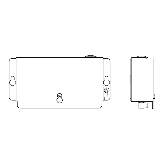
Page 6: Measurements And Component List
Measurements SafeLine SL2 Main unit Article number: *SL2 and component list 41,9 SafeLine SL2 - alarm button and microphone Article number: *LT-stat01 ALARM Button PSTN SafeLine SL2 v.2.1.0 EN... - Page 7 SafeLine SL2 - alarm button, microphone and speaker Article number: *LT-stat02 Speaker ALARM Button PSTN SL2 COP station with speaker Article number: *LT-stat04 Speaker PSTN Surface has to be clean and de-greased to fixate the sticky foam tape on the COP-stations. SafeLine SL2 v.2.1.0 EN...
-
Page 8: Installation
Installation Wiring diagram CAUTION! When using HL1 and/or SafeLine remote station with pictograms, the SL2 is required to be powered with 12V DC. When combining with a GL6 you can connect maximum one SL2 and one HL1. 0 VDC 0 VDC... -
Page 9: Configuration
Configuration Configuration Keyboard configuration The integrated keyboard on the SafeLine board enables a fast overviews configuration of the unit. Unit has to be connected to power source before programming begins! Configuration with SafeLine Pro The unit can be configured at the office prior to the installation or at site after the installation with the help of a configuration cable (*PCable). Use SafeLine Pro v4.02 or later. SafeLine Pro SafeLine SL2 v.2.1.0 EN... - Page 10 Confi guration Remote confi guration For remote confi guration, you can use any PSTN tone dial phone. overviews Dial the phone number of the SafeLine. Enter the function codes on the phone keypad to start the confi guration (password has to be Unit has to be connected to entered). power source before confi guration begins! 1 2 3...
-
Page 11: Configuration Method
Quit configuration Continue configuration? *00*# Enter code and data, eg: *11*012341234# 2 short beeps Call disconnected or end 2 short beeps? of configuration. SL2 will restart with new settings One long beep. Invalid input. Last code has to be re-entered. SafeLine SL2 v.2.1.0 EN... -
Page 12: Configuration Examples
* 8 7 * 0 3 # End configuration: * 0 0 * Example 2 SLCC and 3 day test. (SLCC – SafeLine Call Centre) Start configuration: Enter P100 ID code: * 0 1 * 4 5 6 4 5 6 4 5 #... -
Page 13: Parameter List
Always two digits. Max 3 days according to EN 81-28. 00 = No test alarms Test alarm protocol *31* Protocol test alarm 0 = P100 3 = CPC 4 = Phone number used as ID. SafeLine SL2 v.2.1.0 EN... - Page 14 Recording will be done with the internal microphone of the SL2. Example of message: This is an alarm from the lift on 5th avenue. To hear the this message again, press “1”.
- Page 15 0 = OFF 1 = ON (Default) Auto answer *81* - - # No of signals before SafeLine answers incoming call. Can be set from 00-16 (Default = 02, 00=Unit will not answer). Unit number *82* Program Unit number 1-9 (Default = 0)
- Page 16 Detect dial tone *83* 0 = Off 1 = On (Default) Set to off if SafeLine has problem to detect the dial tone. Receipt to alarm receiver *84* Select which message(s) to send to the alarm receiver at with P100 protocol an alarm call.
-
Page 17: Operation
Call connected The yellow pictogram LED is lit The green pictogram LED turns as soon as the alarm button is on as soon as the SafeLine unit pressed. detects a responding voice. The LED is turned off when the call is terminated. -
Page 18: Testing
Testing Testing the SafeLine SL2 Connect 10-30 VDC SafeLine SL1 will make a self test Green LED flashes 5 times. Yellow LED flashes 5 times. Short tone in the speaker. Long tone in the speaker. Check the mic and Connect telephone line speaker connections Green LED flashes every 5 sec Yellow LED flashes if valid tel. line connected every 5 sec. - Page 19 12 call limit. Line missing or busy Dial tone? Calling 1 phone number. Answer? Calling 2 phone number. Answer? Calling 3 phone number. Answer? Calling 4 phone number. Answer? Alarm operator made connection Emergency call completed SafeLine SL2 v.2.1.0 EN...
-
Page 20: Trouble Shooting
• If the main unit is installed on the car roof, the problem might be due to induction. Do a noise check (**). Poor/distorted sound quality. Volume might be set too loud! Lower the volume and check again. SafeLine SL2 v.2.1.0 EN... - Page 21 Change the antenna position when a call is connected until you shooting find the optimal antenna position. Do not install the antenna near the main unit or close to the wiring. Normally the GSM unit, antenna and SafeLine should have a distance in between of 1,5m. GL6+ >>1.5 m >>1.5 m 0,1m ²...
- Page 22 When none of these solutions apply, install a separate cable for the telephone line. *** Microphone check Call the SL2 and press the following numbers on the caller's phone. Press "4" first to manually switch between the phones. Press "7" to activate the microphone in the lift cabin. Press "*" to activate the caller's microphone. If you can speak through the microphones the hardware is OK.
-
Page 23: Declaration Of Conformity
Rev. 03.016 / Rev. 03.017 / Rev. 03.019 / Rev. 03.025 GL865-Dual V3: 16.00.152 / 16.01.150 / 16.01.153 LE910-EU V2: 20.00.402 SafeLine SL6 4.50 Tyresö, 2020-02-05 Lars Gustafsson, Technical Manager, R&D , SafeLine Group Antennvägen 10, 13548 Tyresö, Sweden +46 (0)8-447 79 32, www.safeline-group.com... - Page 24 SafeLine Group UK Unit 47 · Acorn Industrial Park · Crayford · Kent · DA1 4AL · United Kingdom Tel.: +44 (0) 1322 52 13 96 · info@safeline-group.uk SafeLine is a registered trademark of SafeLine Sweden AB. All other trademarks, service marks, registered trademarks, or registered service marks are the property of their respective owners.
Need help?
Do you have a question about the SL2 and is the answer not in the manual?
Questions and answers