Table of Contents
Advertisement
Quick Links
Advertisement
Table of Contents

Summary of Contents for AVL microIFEM Piezo 4P4x
- Page 1 AT6356E Rev. 01 - 11/2015 AVL microIFEM Piezo 4P4x Product Guide...
- Page 2 COPYRIGHT © AVL LIST GMBH, 2015, ALL RIGHTS RESERVED The contents of this document may not be communicated to any third party without the prior written consent of AVL. Feedback: docu@avl.com...
-
Page 3: Warnings And Safety Instructions
AVL can offer no warranty nor accept any liability if the device is used in applications other than those described and if the necessary requirements are not met and the safety instructions not followed. - Page 4 Warnings and Safety Instructions AVL microIFEM Piezo 4P4x — Product Guide...
-
Page 5: Grouped Safety Messages
When disposing of the product or of parts of it, make sure that the legal regula- tions in force in the country in which the device is operated are observed (e.g. regulations for the disposal of electronic scrap). AVL microIFEM Piezo 4P4x — Product Guide... - Page 6 Grouped Safety Messages AVL microIFEM Piezo 4P4x — Product Guide...
-
Page 7: Table Of Contents
Temperature Range ....................... 20 4 AVL IndiSignal Operating Software................21 Installation ..........................21 AVL IndiSignal View ....................... 22 4.2.1 Toolbar..........................22 4.2.2 Rack View ......................... 23 4.2.3 Transducers and Calibration..................... 23 4.2.4 Status Bar ......................... 23 AVL microIFEM Piezo 4P4x — Product Guide... - Page 8 Signal Input..........................41 Signal Output.......................... 42 Signal Conditioning......................... 42 Data of Other Functions ......................43 Pin Assignment - Front Panel....................44 8.6.1 BNC Socket........................44 8.6.2 4-Pin FISCHER Socket .....................44 8.6.3 FISCHER Triax Socket .....................44 AVL microIFEM Piezo 4P4x — Product Guide...
- Page 9 Transducer Calibration...................... 49 9.1.2 Calibration of the Entire Measurement Chain with Preselected Output Voltage....51 9.1.3 Calibration of the Entire Measurement Chain with Preselected Maximum Pressure..54 9.1.4 Deleting Saved Calibration Data..................59 Index................................61 AVL microIFEM Piezo 4P4x — Product Guide...
- Page 10 Table of Contents AVL microIFEM Piezo 4P4x — Product Guide...
-
Page 11: What You Should Know
For safety reasons, the product is provided with a special seal which may only be broken by AVL personnel. Any unauthorized damage to the seal shall be considered an unauthorized change to the product, which will result in the termi- nation of AVL´s warranty obligation. -
Page 12: Intended Use
Parameterization Calibration and Maintenance Secondary litera- For technical details about the handling of AVL indicating systems, please refer ture to the AVL IndiCom documentation and/or the relevant system manual. 1.5.1 Abbreviations and Glossary Terms Electromagnetic Compatibility Sensor Data Base... -
Page 13: Typographic Conventions
UPPERCASE LETTERS Operating states Programming examples; source code Courier Times New Roman Formulas Menu | Option Description of how to select a menu or menu item AVL microIFEM Piezo 4P4x — Product Guide... -
Page 14: Online Help
We Want to Hear from You Your comments and suggestions help us to improve the quality and practical relevance of our manuals. If you have any suggestions for improvement, please send them to: docu@avl.com We appreciate your feedback! AVL microIFEM Piezo 4P4x — Product Guide... -
Page 15: General
Electrical isolation of each channel's power supply and use of a differential output amplifier ensure that the AVL microIFEM Piezo is also suitable for use in environments with severe interference. The high upper cut-off frequency on the other hand permits highly dynamic measurements. -
Page 16: Options
2.4.2 Cascading Package TI04FCCSA.01 The Cascading Package consists of the following components: 1 serial interface cable (30 cm) 1 power supply cable (30 cm) 1 Y-supply cable for 2 microIFEMs AVL microIFEM Piezo 4P4x — Product Guide... -
Page 17: System Overview And Connections
System Overview and Connections Block Diagram µC COMP. Drift Compensation Device Piezo Amplifier RESET Offset -8 V Analog Output Amplifier ANALOG Lowpass Differential Amplifier A = 1 ... 100 FILTER Fig. 1 Block diagram AVL microIFEM Piezo 4P4x — Product Guide... -
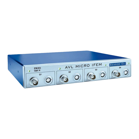
Page 18: Front View
System Overview and Connections Front View AVL MICRO IFEM PIEZO ENSOR Gen 4 Fig. 2 AVL microIFEM Piezo 4P4 A/B/C/D, front view 1 ..Q1 to Q4 Pressure transducer connections: – BNC sockets for pressure transducers with BNC connector –... -
Page 19: Rear View
Connect the RS232 OUT socket of the first AVL microIFEM to the RS232 IN socket of the second AVL microIFEM. Connect the 9.5 ... 36 V DC OUT socket of the first AVL microIFEM to the 9.5 ... 36 V DC OUT IN socket of the second AVL microIFEM. -
Page 20: Temperature Range
E.g.: 12 V DC power supply: 15 W/12 V = 1.25 A, i.e. 6 racks can be cascaded. EnsureAlso ensure that the start-up power consumption (22 W for each unit) of all AVL microIFEM units does not exceed the maximum power output of the power supply! The power supply unit TR70 can supply up to four AVL microIFEM units. -
Page 21: Avl Indisignal Operating Software
AVL IndiSignal is an integral part of parameterization in AVL IndiCom. Not only the data acquisition hardware, but also the AVL microIFEM is visualized. In this case, it is not necessary to do a separate AVL IndiSignal installation. • Set the relevant COM port in the IndiSignal section within the indicom.ini file. -
Page 22: Avl Indisignal View
Calling up a properties menu and reloading amplifiers or sensors will also deac- tivate the function. Reset Piezo Amplifiers Resets all installed piezo amplifiers in all available racks, i.e. sets their output voltage to 0 V or -8 V. AVL microIFEM Piezo 4P4x — Product Guide... -
Page 23: Rack View
Firmware revision and SID identification hardware generation are also shown. Help Calls the online Help. Refresh Sensor Data Reloads the sensor data of all connected sensors (AVL SDC, SID, SDB) into the relevant amplifier. 4.2.2 Rack View This section displays the selected AVL microIFEM. Devices can be selected in the status bar at the bottom of the window. -
Page 24: General Information About Calibration
These parameters are stored in a non-volatile memory in the amplifier. If the TEDS (AVL SDC), SID or SDB functions are activated for a piezo trans- ducer, the system will read in type, serial number and sensitivity from the data connector or the database. - Page 25 Transducer Type / Serial Number For documentation of your measured data in conjunction with AVL IndiCom, enter transducer type and serial number. Information If this amplifier has already been calibrated with a dead weight tester, the cali- bration parameters are locked for input (see Calibration with Dead-Weight Tester (IndiSignal Stand-alone Only) on page 49).
- Page 26 The following options are available: 12, 20, 30, 50, 100 kHz Information The real filter frequencies may differ by around 10 %. Please note that low filter frequencies will lead to a signal delay. AVL microIFEM Piezo 4P4x — Product Guide...
-
Page 27: Sensor Data Management
Selecting the check box TEDS (SDC) activates the reading of the sensor data from a connected TEDS element (TEDS = Transducer Electronic Data Sheet). Depending on the type of AVL microIFEM, this can be a TEDS with FISCHER triax socket or with a 4-pin FISCHER socket (AVL SDC). The system will auto- matically use the optimal transducer sensitivity, depending on the set signal input range. -
Page 28: Functions
A central sensor database is required to use this function. For installation and operation of the sensor database, use the program SensorAdmin, which is available under Tools on your AVL IndiSignal CD-ROM or in the IndiSignal installation folder. To activate this database, use the program ActivateSensorDataBase.exe, which is available in the AVL IndiSignal installation folder. -
Page 29: Calibration Info Tab
AVL IndiSignal Operating Software input in AVL IndiCom is needed, because the software reads out the SCF auto- matically. If the maximum pressure that occurs during operation is not known, we recom- mend starting with a high initial value and then reducing it until the piezo ampli- fier goes into saturation (check by means of LED or overrange check;... -
Page 30: Presettings
Presettings By changing entries in the indicom.ini file it is possible to specify settings which cannot be defined via the user interface. With AVL IndiCom, you can find these settings in the [IndiSignal] section of the indicom.ini file. Entry... -
Page 31: Sensor Data Management
Sensor Data Management Sensor Data Management The AVL microIFEM Piezo 4P4x enables you to read the characteristic trans- ducer data from a sensor data connector or a database (either manually or auto- matically via SID). This includes both calibration values and sensor runtimes. - Page 32 Total operating time of the sensor. When you start AVL IndiCom, the operating time counter in the amplifier is set to 0. As soon the amplifier gets a cylinder pressure signal, this internal counter recognizes the duration. When AVL IndiCom is stopped, the current counter content will be added to the field Total Operating Time.
- Page 33 By clicking Edit you can switch to the Edit mode, which enables you to edit the values in the Property column. At the same time, the button Burn is enabled which allows you to save the modifications in the AVL SDC. Close Closes the dialog. AVL microIFEM Piezo 4P4x — Product Guide...
- Page 34 Sensor Data Management AVL microIFEM Piezo 4P4x — Product Guide...
-
Page 35: Optimizing The Signal Quality
To comply with the Electromagnetic Compatibility (EMC) directive it is neces- sary to mount a clamp-on ferrite core onto the input signal cable (included in scope of supply): Ferrit Core Piezo Amplifier Fig. 10 Position of ferrite core (thick cable) AVL microIFEM Piezo 4P4x — Product Guide... -
Page 36: Piezo Signal Conditioning
You can choose between 0 V and -8 V offset voltage. NOTICE If the cylinder pressure signal is no longer detected (signal period > 1.2 s or amplitude < average value [V] +0.7 V), Continuous mode is automatically selected. AVL microIFEM Piezo 4P4x — Product Guide... -
Page 37: Extended Output Range
If the LED on the flashes red, this indicates a brief or longer saturation of the amplifier. Reset the amplifier. If necessary, reduce the gain by entering a higher value in the Signal Input Range input field. Also check cable connections. AVL microIFEM Piezo 4P4x — Product Guide... - Page 38 Optimizing the Signal Quality AVL microIFEM Piezo 4P4x — Product Guide...
-
Page 39: Maintenance
Maintenance Accuracy On a regular basis (typically once a year): Check of the amplifier's accuracy. For this check, AVL provides the AVL Amplifier Calibration Unit. Article: TI04CALUA.01 Amplifier Calibration Unit Drift The high isolation resistance of piezo amplifiers at the time of delivery can only be maintained if the devices are always kept dry and clean. - Page 40 If there is still too much drift, dry the amplifier for 6 hours at +70° C. Information If none of these measures solves the problem, the amplifier needs cleaning inside as well. This should only be done by the manufacturer. AVL microIFEM Piezo 4P4x — Product Guide...
-
Page 41: Technical Data
218 x 42 x 230 mm (width x height x depth). Depth including cable connections: 250 mm Weight 1 AVL microIFEM = 1.5 kg19" tray incl. 2 pieces AVL microIFEM = 4 kg Ambient temperature -40 °C ... +60 °C (See also External Power Supply on page 16.) -
Page 42: Signal Output
Asymmetric, output ground connected to protective ground and can be decou- pled from the input ground by means of a differential amplifier. Connection BNC socket on the rear panel of the AVL microIFEM. Voltage -11 V ... +11 V at load >333 ohms Current +30 mA max. -
Page 43: Data Of Other Functions
Drift-free measurement without any effect on amplitude and phase T >1.2 s: Continuous drift compensation Output signal lift = 0.7 V out min Minimum output signal lift for drift compensation to function properly. AVL microIFEM Piezo 4P4x — Product Guide... -
Page 44: Pin Assignment - Front Panel
Fig. 13 4-pin FISCHER socket (only 4P4 E/F/G/H) 8.6.3 FISCHER Triax Socket Assignment Signal Pin 1 Charge signal Pin 2 TEDS Data Pin 3 Ground Pin 4 Not used Tab. 3 Fig. 14 FISCHER triax socket (only 4P4 A/B/C/D) AVL microIFEM Piezo 4P4x — Product Guide... -
Page 45: Pin Assignment - Rear Panel
Pin 9 Not used Not used Socket housing Cable shield (protective Cable shield (protective ground) ground) Tab. 4 Fig. 15 9-pin Sub-D connector RS232 OUT (X7) Fig. 16 9-pin Sub-D socket RS232 IN (X8) AVL microIFEM Piezo 4P4x — Product Guide... -
Page 46: Connectors 9.5
Pin 13 Ground Pin 16 RESET CH1 Pin 17 RESET CH2 Pin 18 RESET CH3 Pin 19 RESET CH4 Socket housing Cable shield (protective ground) Tab. 6 Fig. 18 25-pin Sub-D connector X9 AVL microIFEM Piezo 4P4x — Product Guide... -
Page 47: Socket For Connector X9
Tab. 7 Fig. 19 37-pin Sub-D socket for connection to connector X9 CE Compliance The AVL microIFEM Piezo 4P4x complies with the following directives and stan- dards: 2004/108/EC Electromagnetic Compatibility Directive complied with by virtue of compliance with the following Standard: EN 61326-1:06 Electrical Equipment for Measurement, Control and Labora- ... - Page 48 Technical Data AVL microIFEM Piezo 4P4x — Product Guide...
-
Page 49: Appendix
The selected calibration pressure is 120 bar, the voltage at ambient pressure is set to -8 V. Fig. 20 Transducer Calibration If you want to calibrate the transducer with a dead-weight tester, activate the Transducer Calibration check box. AVL microIFEM Piezo 4P4x — Product Guide... - Page 50 Without Pressure Weight input field. 10. Apply the calibration pressure. 11. Read the output voltage with calibration pressure and enter this voltage value in the With Pressure Weight field. AVL microIFEM Piezo 4P4x — Product Guide...
-
Page 51: Calibration Of The Entire Measurement Chain With Preselected Output Voltage
If you want to calibrate the entire measurement chain using a dead weight tester with preselected output voltage, activate the Measuring chain cali- bration check box and click the Output voltage predefined option button. AVL microIFEM Piezo 4P4x — Product Guide... - Page 52 Click Next. Fig. 26 Measured voltages with predefined output voltage Click Reset to reset the charge amplifier to its original status. When doing so, ensure that ambient pressure is applied to the transducer. AVL microIFEM Piezo 4P4x — Product Guide...
- Page 53 Estimated Transducer Sensitivity and the Calibration Wizard's Measured Voltages dialog will be displayed. 14. Carry out the calibration once again as described. Fig. 28 Measured voltages (adjusted) with predefined output voltage AVL microIFEM Piezo 4P4x — Product Guide...
-
Page 54: Calibration Of The Entire Measurement Chain With Preselected Maximum Pressure
If you want to calibrate the entire measurement chain using a dead weight tester with preselected maximum pressure, activate the Measuring chain calibration check box and click the Maximum pressure predefined option button. AVL microIFEM Piezo 4P4x — Product Guide... - Page 55 Without Pressure Weight input field. 11. Apply the calibration pressure. 12. Read the output voltage with calibration pressure and enter this voltage value in the With Pressure Weight field. AVL microIFEM Piezo 4P4x — Product Guide...
- Page 56 14. Carry out the calibration once again as described. Fig. 34 Measured voltages (adjusted) with predefined maximum pressure 15. Enter the measurement values in V and click Next. Fig. 35 Calibration results (adjusted) with predefined maximum pressure AVL microIFEM Piezo 4P4x — Product Guide...
- Page 57 16. Click Finish to close the Calibration Wizard. The calibration values of the entire measurement chain including the pres- sure transducer are stored in the amplifier of the AVL FlexIFEM and can be checked on the Calibration Info tab in the Properties dialog.
- Page 58 Carry out the calibration once again as described. Enter the measurement values in the corresponding fields and click Next. Fig. 40 Measured voltages (adjusted) with predefined output voltage for all piezo amplifiers AVL microIFEM Piezo 4P4x — Product Guide...
-
Page 59: Deleting Saved Calibration Data
• Click the Unlink button on the Calibration Info tab within the Properties dialog. The password to unlock the calibration values is defined in the indisignal.ini file (entry CalPW =). AVL microIFEM Piezo 4P4x — Product Guide... - Page 60 Appendix AVL microIFEM Piezo 4P4x — Product Guide...
-
Page 61: Index
… 24 gain pin assignment … 42 error … 44 front panel … 42 factor … 45 rear panel glossary … 12 plausibility check … 3 grounded input … 26 polarity … 42 AVL microIFEM Piezo 4P4x — Product Guide... - Page 62 … 42 toolbar … 22 total operating … 32 cycles … 32 time transducer calibration … 49 triax … 11 UNIT ADDRESS … 19 unlock calibration values … 59 upper cut-off frequency … 43 AVL microIFEM Piezo 4P4x — Product Guide...
- Page 64 FOR FURTHER INFORMATION PLEASE CONTACT: AVL List GmbH, Hans List Platz 1, 8020 Graz, Austria Phone: +43 316 787-0, Fax: +43 316 787-400, eMail: info@avl.com, www.avl.com...
Need help?
Do you have a question about the microIFEM Piezo 4P4x and is the answer not in the manual?
Questions and answers