
Summary of Contents for S3 CS808
- Page 1 CS808 CNC Motion Controller User's Guide: 1.0 3-17-2020 CS808 User's Guide CNC 4 Axis Stepper and Servo Machine Controller CS808 Servo Version © Stepper3 LLC 2020 Page 1 of 16...
-
Page 2: Features
19 24V inputs for home switches, While a versatile product for new machines and touchpads, sensors, start/stop switches, retrofits of many kinds, CS808 was designed as a and more direct replacement for Chinese controllers. It is Can be configured to be used with S3CNC, designed, built, tested and supported in the USA. -
Page 3: Table Of Contents
User's Guide: 1.0 3-17-2020 Table of Contents FEATURES ............................2 ............................ 2 RODUCT RIEF CS808 CONTENTS ..........................2 TABLE OF CONTENTS ........................... 3 1: CS808 OVERVIEW ..........................4 1.1: 24VDC I ..........................5 NPUT 1.2: I ........................ 5 NPUT AND UTPUT 1.3: 100M... -
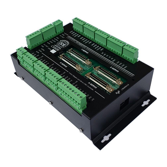
Page 4: 1: Cs808 Overview
User's Guide: 1.0 3-17-2020 1: CS808 Overview The Stepper3 LLC CS808 is a general purpose 4 axis stepper and servo CNC controller. Below is an annotated diagram of all of the physical connections that can be made to the controller and features such as LEDs, Ethernet motion control interface, and the product version. -
Page 5: 24Vdc Input
CS808 CNC Motion Controller User's Guide: 1.0 3-17-2020 1.1: 24VDC Input The image above shows the connector location for the 24V power input. There is an LED indicator light that shows that power is present. The minimum required power supply must be at least a 25W 24V power supply (such as Meanwell P/N: RS-25-24). -
Page 6: Charge Pump Safety Circuit
User's Guide: 1.0 3-17-2020 1.4: Charge Pump Safety Circuit The CS808 features a built-in charge pump safety circuit. This ensures that without connection to the host computer software or when the software is disabled, none of the outputs can be activated. In order to enable the charge pump, you must configure the signal in the S3CNC, Mach4, or Mach3 software as below. -
Page 7: 3: Digital Inputs
3: Digital Inputs The CS808 consists of 3 digital inputs per axis and 7 general purpose digital inputs for a total of 19 digital inputs. The inputs are sinking (wire one terminal of a switch to ground) or NPN (use NPN sensors). -
Page 8: Ether-Mach Pinouts
CS808 CNC Motion Controller User's Guide: 1.0 3-17-2020 3.2: Ether-Mach Pinouts X Axis Pinouts CS808 Pin Name Ether-Mach Port and Pin Description XLIM- Port 1 Pin 10 X Negative Limit Switch XLIM+ Port 2 Pin 10 X Positive Limit Switch... - Page 9 CS808 CNC Motion Controller User's Guide: 1.0 3-17-2020 Z Axis Pinouts CS808 Pin Name Ether-Mach Port and Pin Description ZLIM- Port 1 Pin 12 Z Negative Limit Switch ZLIM+ Port 2 Pin 15 Z Positive Limit Switch ZORG Port 1 Pin 3...
-
Page 10: 4: Digital Outputs
4: Digital Outputs The CS808 consists of 5 digital outputs for spindle control and 3 general purpose digital outputs for a total of 8 digital outputs. The outputs are open drain and can sink up to 500mA through a load. The following section shows the output schematic as well as an example for wiring. -
Page 11: Ether-Mach Pinouts
CS808 CNC Motion Controller User's Guide: 1.0 3-17-2020 4.2: Ether-Mach Pinouts Spindle Control Pinouts CS808 Pin Name Ether-Mach Port and Pin Description Port 1 Pin 1 Spindle Counter Clockwise Port 2 Pin 1 Spindle Clockwise Port 3 Pin 16 Digital Spindle Speed Bit 2... -
Page 12: 5: 4-20 Ma Analog Output
Depending on the version of the CS808 controller you have, you will either see 4 50 pin Mini D Ribbon cable connectors or a black cover plate in center of the CS808 near the X, Y, Z, and A servo labels. -
Page 13: Step And Direction Outputs
The table below shows the pinouts for these signals. It also shows the CS808 signals the Yaskawa signals are electrically connected to so that you do not connect anything to the terminal blocks. The X, Y, Z, and A motors all share the same enable and reset outputs. -
Page 14: 7: Ether-Mach And S3Cnc
User's Guide: 1.0 3-17-2020 7: Ether-Mach and S3CNC If you are using S3CNC, please see the S3CNC manual for configuring your I/O. All I/O for the CS808 controller can be setup within the S3CNC configurator. If you are using Mach3 or Mach4, you may reference the Ether-Mach plugin and manuals at ether- mach.com. -
Page 15: 8: Electrical Ratings
CS808 CNC Motion Controller User's Guide: 1.0 3-17-2020 8: Electrical Ratings Units Typ. DC Input Input Voltage (VIN) Input Current @ 24VDC Digital Inputs Input sink current Digital Outputs Maximum Sink Current DC Voltage 4-20 mA Analog Output Output Current... -
Page 16: 9: Physical Dimensions
User's Guide: 1.0 3-17-2020 9: Physical Dimensions The CS808 controller box is 8.625” x 5.08” x 2.1” and weighs approximately 5 lbs. There are four 0.29” mounting holes on extruded tabs. A detailed drawing of the bottom is shown below (dimensions shown in inches).
Need help?
Do you have a question about the CS808 and is the answer not in the manual?
Questions and answers