Table of Contents
Advertisement
Quick Links
Advertisement
Table of Contents

Related Manuals for Samon GLACIAR X5


Summary of Contents for Samon GLACIAR X5
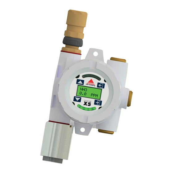
- Page 1 GLACIÄR X5 Advanced Gas Detection Transmitter USER MANUAL GLACIÄR X5 Manual v3...
-
Page 2: About This Manual
INTRODUCTION The GLACIÄR X5 gas detector transmitter is a standalone detector approved for zone 1, 2, 21 or 22 ATEX environments. X5 is approved to both European, UK ATEX and international IECEx standards. The transmitter features a non-intrusive calibration, one or two independent detectors, 2 analogue outputs, relays and a wide range of sensor options. - Page 3 The relationship between the output signal and the gas concentration is linear, the control panel interprets the sig- nal and the gas level is displayed on the HMI display. SAMON holds evidence of this linear performance which is available upon request.
-
Page 4: Specifications
SPECIFICATIONS 3 off M20 x 1.5 Ports Fit up to 2 Gas Detectors to M20 x 1.5 Ports See Options Power 18 to 30V DC 2804 2585 Electrical Outputs 2 off independent 4-20mA outputs auto ranged to suit fitted detector(s) 1 Single Pole Fault Relay 2 SPCO Alarm Relays Relays 4A at 24V DC Non Inductive... -
Page 5: Installation Instructions
MARKINGS Serial TOCSIN Serial Serial D.O.M T T OCSI OCSIN N Oliver IGD Ltd II 2G Ex db IIC T6/T5 Gb Crosby St INSTALLATION INSTRUCTIONS II 2D Ex tb IIIC T85ºC/ T100ºC Db Stockport Ta = -20ºC to +40ºC/+55ºC SK2 6SH UK IECEx EXV 16.0002X ExVeritas 16 ATEX 0140X ExVeritas 21UKEX0913X... - Page 6 CUSTOMER SEALING AND EARTHING REQUIREMENTS The JB3 is designed for use in Zone 1 and Zone 2 hazardous areas and is ATEX & IECEx certified. To maintain compliance it is imperative the installer of the equipment observes the following installation guidelines. Failure to do so could compromise the protection concept of the equipment.
- Page 7 CONSIDERATIONS FOR ATEX INSTALLATIONS The following notes on equipment selection and installation are taken from applicable standards. They are not intended to replace adequate knowledge and skill on the part of those using them. Also any and all applicable local regulations should be considered when deciding on installation methods and materials.
-
Page 8: Maintenance
CONSIDERATIONS FOR ATEX INSTALLATIONS Un-used cores of a multi-core cable Any un-used cores in a multi-core cable must be either terminated to earth, or effectively isolated from other cores and terminations. We recommend terminating to the internal earth stud. Maintenance Whilst the maintenance of installations is the responsibility of the site operator, EN 60079-17 gives guidance on what should be checked and when. - Page 9 ATEX INSTALLATION CHECKLIST Page 9...
- Page 10 ATEX INSTALLATION CHECKLIST Page 10...
-
Page 11: Typical Operational Displays
OVERVIEW X5 has 5 20mm x 1.5 threaded entries. Two of these can be used to mount 102 series gas detectors. Which port is used for each detector has an impact on how it Buttons that can be accessed using the is displayed on screen (sensor A or B). - Page 12 BASE PCB CONNECTIONS On first delivery it will be necessary to connect a sensor or sensors to the X5 and check the X5 correctly registers and installs them. a) Unscrew the X5 cover noting that it may be necessary to loosen the locking screw. b) With the lid unscrewed, unscrew the PCB retention screw using the Allen key provided.
- Page 13 BASE PCB CONNECTIONS Analogue Outputs Power 24V DC (18 to 30V DC) Power 24V DC No Polarity (18 to 30V DC) Highway Connection No Polarity Highway Connection Fault Relay Auxiliary Normally Power Energised Rated 0.5A Max Sensor B Sensor A Connector Connector Alarm Level 1...
- Page 14 CONNECTORS X5 uses screwless spring loaded terminals for greater connection reliability. Strip the wire to the correct length. Use a 3mm flat bladed screw driver to ‘open’ the terminal gate. Insert the cable and remove the screw driver to ‘close’ the terminal gate. Cable strip lenght 5mm Ideally terminate direct to solid core or stranded copper cable...
- Page 15 POWER AND ANALOGUE OUTPUT CONNECTIONS The following diagram shows typical connection for a 24V DC power X5 with both its analogue 4-20mA output connected to a host system. The ammeter is shown in circuit if required for test purposes. Cables must be screened types.
- Page 16 RELAYS X5 has 3 relays on-board. Fault Relay: This is normally energised in operation providing a closed connection that opens (de-energises) if a fault condition is detected. AL1 & AL2 Relays: By default these are normally de-energised and energise on breaching an alarm level. Note that alarm levels are automatically set based on the range and gas type of the detector(s) fitted.
- Page 17 GLACIÄR SERIES PRODUCTS GLACIÄR MIDI GLACIÄR MIDI - our flagship refrigerant gas detector - detect all commonly used refrigerants with only 5 different sensor types, making it simple and easy to select the right detector for your application. GLACIÄR MICRO GLACIÄR MICRO - your compact solution to refrigerant leak detection, tailored for seamless integration into OEM equipment.
- Page 18 REMOTE CONNECTION OF ONE OR BOTH DETECTORS X5 allows one or both detectors to be remotely connected to the X5 head unit. The following drawings indicate general arrangement and wiring requirements. This allows the Serial Serial Remote JB3 ATEX Junction Model Model D.O.M...
- Page 19 REMOTE CONNECTION OF ONE OR BOTH DETECTORS End of Line Terminators Must be Fitted at the Last Module in Line as Indicated Across the L1 and L2 Terminals. Terminators are Shipped With The Remote Sensors. External PSU 24V DC 0V DC Failure to Fit Terminators Will Prevent System Operation L1 L2...
- Page 20 ON START UP SOFT VER SERIAL POWER 1.45 10058420 On power up the display back light will show blue with the status indicators cycling red, yellow, green. The display shows the software version and serial number. CHAN A CHANNELS 100 PPM The status indicator stays green if the gas detectors are connected otherwise a channel fault is indicated for the affected channel.
- Page 21 ON START UP WARMUP CHANNEL 25 %VOL 900 S During warm up information is displayed to show the setup of the X5. If two channels are fitted information is displayed sequentially. BASE WARMUP ADD 53 25 %VOL 356 S If addressable mode is active then the base address for the unit is also displayed sequentially. The display then indicates the warm up time, this is variable depending on the detector type.
-
Page 22: Day To Day Operation
DAY TO DAY OPERATION In Normal Condition Detector A (left port) Channel Detector B (right port) Gas Type Current Reading 235 PPM Status Indicator Green In Alarm Condition Status Indicator Red flashes red In alarm mode the status indicator bar ▶... -
Page 23: Menu System
MENU SYSTEM 235 PPM To enter the menu system hold the magnetic wand over the ENTER symbol for at least 5 seconds. Data Entry Data entry operates in the same manner for passwords, calibration data etc. At any moment you are editing one of the digits on screen. -
Page 24: Menu Selection
MENU SELECTION Enter Password 100 to access the menu system. Use the up/down icons to navigate between the two menu options Select the enter Icon to select the option PASSWORD or exit icon to return to normal operation OPTION OPTION OPTION SETUP ALARMS... - Page 25 CALIBRATION..THE ZERO ROUTINE At the start of the cal and zero process you are asked to check and change the date if necessary. Use the data entry method previously described to do this. This information is saved PASSWORD into the calibration log and can be retrieved to provide a record of calibration activities. Note the calibration option is not available unless you have successfully completed a zero within 12 hours.
- Page 26 CALIBRATION At the start of the cal and zero process you are asked to check and change the date if necessary. Use the data entry method previously described to do this. This information is saved PASSWORD into the calibration log and can be retrieved to provide a record of calibration activities. Note the calibration option is not available unless you have successfully completed a zero within 12 hours.
- Page 27 CAL mA PASSWORD To undertake this process you will need a calibrated mA meter and either the X5 is connected to a OPTION OPTION OPTION suiatable control input as shown or a PSU with the SETUP ALARMS ”sense” resistor as indicated in circuit. ZERO Select option to Zero or Calibrate SELECT...
- Page 28 FORCE READING PASSWORD OPTION OPTION OPTION SETUP ALARMS FORCE READING SELECT Select either channel A or B. A: H2S Increase the reading using the icons to the gas level you wish to force. 00 PPM The display now shows the forced reading as if it were a real gas reading. After the alarm delay period if alarm levels are breached then the X5 will go A: H2S into alarm mode a if this were a real gas reading.
- Page 29 FORCE FAULT PASSWORD OPTION OPTION OPTION SETUP ALARMS FORCE FAULT SELECT Select either channel A or B The display now shows the forced under range fault as if it were a real fault. After the fault delay period the X5 will go into fault mode as if this were a real fault. Relays, mA outputs and returned addressable readings will all act as if this were a real fault.
- Page 30 SETUP MENU..ENGINEER FUNCTIONS PASSWORD OPTION OPTION OPTION SETUP ALARMS These menu items Do not ADDRESS SET AL1 show in addressable mode. MODE LEVEL When this option is selected the control panel controls these functions. CONC SET AL1 CLAMP TYPE These menu items Do not FAULT SET AL2...
- Page 31 SETUP MENU..ENGINEER ALARMS Use the up and down icons to navigate up and down menus OPTION Use the enter icon to select a menu option ALARMS Use the exit icon to return to a previous stage Note if address mode is on then alarm levels and relay actions are controlled from the host controller and the following menu options will not be displayed Use these menu options to set the required alarm levels and the alarm actions SEL AL1...
-
Page 32: Set Alarm Delay
SET ALARM LEVEL 1 OR 2 Alarm levels can be adjusted from the default pre-sets. In the PASSWORD option menu select either set AL1 or set AL2 as desired. The existing alarm level is displayed, note that units are not shown. - Page 33 SET ALARM DELAY PASSWORD The X5 allows you to set an alarm delay of up to 99 seconds. The default value is 10 seconds. This value is the length of time a gas level must be above the set alarm level before the alarm operates. The setting is OPTION OPTION typically used to allow the X5 to ignore short duration gas...
- Page 34 FORCE RESET Force reset does two things 1. The X5 restarts and checks its inputs to see what gas de- PASSWORD tectors are fitted. Once detected, the channels are added with ranges, units, gas types and alarm levels loaded from the sensor.
-
Page 35: Communication Test
COMMUNICATION TEST PASSWORD The comm’s or communications test is used to test the quality of serial communication when detectors are connected remotely from the X5. OPTION OPTION If this option is run with detector(s) in direct connection mode SETUP then the error message ” ”... -
Page 36: Remote Sensor
REMOTE SENSOR Detectors can either be directly connected to the X5 via the PASSWORD X5 motherboard or can be remotely connected on a 2-Wire addressable highway. (See section Remotely Connecting Sensors). OPTION OPTION By default the X5 will have detectors directly connected to SETUP the X5 motherboard. -
Page 37: Fault Delay
FAULT DELAY PASSWORD Use this menu item to set the delay period in seconds before the fault relay/indication activates. OPTION OPTION This setting allows you to make the system more or less SETUP responsive to system faults, particularly comm’s errors. FAULT As with alarm relays, the delay set means that the fault must DELAY... - Page 38 ACCESSORIES ATEX Cable Gland Pole Clamp ATEX M20 Stopping Plug The X5 Gas Detector Trans- mitter can be fitted with a Disk Filter splash guard. The splash guard is fitted when the X5 is placed in locations where it is liable to come ATEX Splash Guard into contact with water.
- Page 39 NOTES Page 39...
- Page 40 Sold by: SAMON AB Modemgatan 2 S-235 39 Vellinge Sweden Manufactured by: IGD - International Gas Detectors Stockport, UK Part of Safe Monitoring Group www.samon.com...
Need help?
Do you have a question about the GLACIAR X5 and is the answer not in the manual?
Questions and answers