Advertisement
Advertisement
Table of Contents

Related Manuals for LIMIT 20


Summary of Contents for LIMIT 20
- Page 1 Digital Clamp Meter Operating manual...
- Page 2 Illustrations Fig 2. Current measurement AC Fig 1. Voltage measurement DC and AC Fig 4. Replacing battery Fig 3. Diode test Continuity test Resistance...
- Page 3 Voltage Range Resolution Accuracy Overload Protection 2.000V 20.00V 10mV ±(1.2%+5) 200.0V 100mV 600V ms 600V ±(1.5%+5) DC Voltage Range Resolution Accuracy Overload Protection 200.0mV 100mV ±(0.8%+3) 2.000V 20.00V 10mV ±(0.8%+1) 600V DC rms 200.0V 100mV 600V ±(1%+3) Resistance Range Resolution...
- Page 4 Range Resolution Accuracy Overload Protection 100mV Display approximate 600Vp forward voltage drop : 0.5V~0.8V AC Current Range Resolution Accuracy Frequency Overload Response Protection 2.000A 0.001A ±(4%+20) <0.4A ±(3%+12) 20.00A 0.01A ±(3%+12) 50Hz~60Hz 400A rms <0.4A ±(2%+8) 200.0A 0.1A 400A ±(1.5%+5)
- Page 5 Svenska ......11-15 Norsk ....... .16-20 Dansk .
-
Page 6: Table Of Contents
English Contents Overview General specification Safety information Voltage DC and AC Current AC Resistance Diode test Continuity test Battery... -
Page 7: Overview
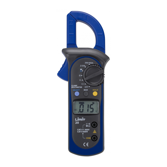
Please read the relevant information carefully and observe all the Warnings and Notes strictly. Limit 20 is a clampmeter/multimeter for professional use. The instru- ment have autorange and the display have large digits, shows rotary switch position witch makes this instrument easy to handle for the user. - Page 8 English test, adhere to the following rules: • Before using the Meter inspect the case. Do not use the Meter if it is damaged or the case (or part of the case) is removed. Look for cracks or missing plastics. Pay attention to the insulation around the connectors.
-
Page 9: Voltage Dc And Ac
Never attempt an in-circuit current measurement where the vol- tage between terminals and ground is greater than 600 V. 1. Set the rotary switch to 2/20 A or 200/400 A position. 2. Open the jaws and center one of the conductor. Only one con- ductor at each time can be measured. -
Page 10: Diode Test
English Note • The test leads can add 0.1Ω to 0.3Ω of error to resistance mea surement. To obtain precision readings in low-resistance measure- ment, that is the range of 200Ω, short-circuit the input terminals beforehand and record the reading obtained. This is the additional resistance from the test lead. - Page 11 4. Connect the test leads across with the object being measured. The buzzer sounds if the resistance of a circuit under test is less than 50Ω. Replacing the Battery (see fig 4) 1. Disconnect the connection between the testing leads and the cir- cuit under test when battery indicator appears on the display.
Need help?
Do you have a question about the 20 and is the answer not in the manual?
Questions and answers