
Related Manuals for Digital Alert Systems R190A

Summary of Contents for Digital Alert Systems R190A
- Page 1 Instruction Manual LAN Hub Controller Model R190A Digital Alert Systems, Inc. 100 Housel Ave Lyndonville NY 14098-0535 585-765-2254 fax 585-765-9330 www.digitalalertsystems.com 1340221 09082023...
-
Page 2: Table Of Contents
Table of Contents Warranty Return Policy to Factory Specifications Front and Rear View EAS Overview EAS Getting Started Operation Remote Control Overview Remote Control Getting Started... -
Page 3: Warranty
This warranty does not apply to instruments or sub-assemblies subjected to abuse, abnormal operating conditions, or unauthorized repair or modification. Since Digital Alert Systems, Inc. has no control over conditions of use, no warranty is made, or implied as to the suitability of our product for the customer's intended use. -
Page 4: Specifications
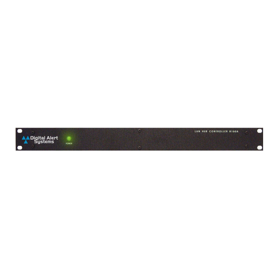
Specifications Number of relays 4 Individually controlled rated for 1Amp at 28 Volts DC, SPDT, NO, NC. Latch ON, Latch OFF, and Momentary from .1 to 86,400 Seconds. Connections 10/100 baseT via RJ45 Power requirements + 12 volts DC; 100-240 VAC wall unit supplied. Indicator lights One (1) to indicate Power on the front panel. -
Page 5: Front And Rear View
Front View Rear View... -
Page 6: Eas Overview
EAS Overview The Digital Alert Systems’ R190A Hub Controller provides the ability to switch equipment at a remote site or CATV Hub during EAS Alerts. It uses a LAN or WAN connection from a control device such as the DASDEC EAS Encoder/Decoder. -
Page 7: Eas Getting Started
192.168.1.2 will be visible on the network or will not clash with an existing node. Once the R190A is powered up it can be accessed via a web browser from any remote computer on the LAN routed to see the address 192.168.1.2. - Page 8 Setup Configuration – The Setup mode of the R190A permits several custom settings, these include the unit’s IP address, Netmask, Gateway, network speed, mode and passwords. No username is required to log into Setup, and the default password is shown in bold between the quotes “digital”. The following screenshots show the setup pages.
- Page 10 Setup or the Control password, click on the “Submit” button. If the password(s) are forgotten, the R190A can be reset to factory defaults by removing the power from the unit, pressing, and holding the Reset button on the back of the unit, and reconnecting the power to the unit.
-
Page 11: Operation
Clicking on the button, On, Off, or Pulse, on the desired relay will allow you to test that the device being controlled by the R190A is functioning properly. The color of the relay status will change from red to green when the relay is closed. - Page 12 Enter the new IP address for the R190A as shown in the following screen. The DASDEC will attempt to ping the R190A and display the status. Verify that the status is OK. Accept changes.
- Page 13 Select the required condition to close each relay. Once selected the Activating FIPS and Activating EAS Codes boxes will be displayed. The default setting is “Any FIPS” and “Any EAS Codes” which triggers the relay when an alert is detected. Setup >...
- Page 14 Click on the “EAS Group” link to select EAS codes from the EAS pools. When the desired FIPS codes are selected click the “Accept Changes” button and they will be added to the FIPS list to the right. When finished, return to Setup > Net Alerts > Net GPIO Repeat this step for all of the required relays.
-
Page 16: Remote Control Overview
Remote Control Overview In its basic configuration, the R190A is a simple remote control that allows the user to command 4 DPST relays at a remote location. These commands can be issued from any computer with a web browser through a network connection to the R190A. -
Page 17: Remote Control Getting Started
EAS applications. Follow the steps in the EAS Getting Started section to set the device IP address for your network. Setup Configuration – The Setup mode of the R190A allows you customize several settings, including the unit’s IP address, Netmask, Gateway, network speed, mode and passwords. - Page 18 Click NETWORK to change the IP address and other Network settings.
- Page 19 Setup or the Control password, click on the “Submit” button. If the password(s) are forgotten, the R190A can be reset to factory defaults by removing the power from the unit, pressing and holding the Reset button on the back of the unit, and reconnecting the power to the unit.
- Page 20 Relay Configuration From the main menu, click the Relay 1 tab to setup how the relay 1 section of the control page will be displayed. Main Header - If desired, enter text to be displayed for the main header on the control page.
- Page 21 Clicking on the button, On, Off, or Pulse, on the desired relay will allow you to test that the device being controlled by the R190A is functioning properly. The color of the relay status will change from red to green when the relay is closed.
- Page 22 Applications The R190A will control any device within the power limits of its relay contacts. Adding a power relay that is energized by the R190A can control devices consuming additional power. The R190A will control all of the contact closure operated switches manufactured by Digital Alert Systems.
Need help?
Do you have a question about the R190A and is the answer not in the manual?
Questions and answers