
Related Manuals for SOOKOOK P3M

Summary of Contents for SOOKOOK P3M
- Page 1 GAS Burner Sookook Corporation Installation / Operation / Maintenance www.sookook.co.kr...
-
Page 3: Table Of Contents
Sookook Corporation Contents Warnings PART 1 : Technical Specification 1A. Product Introduction 1B. Burner Specifications 1C. Burner Performance Curve 1D. External Dimensions 1E. Parts Description 1F. Burner Installation 1G. Gas Valve Train 1H. Burner Circuit Diagram PART 2 : Operation 2A. - Page 4 Sookook Corporation Warnings This manual is one of the key items supplied with the burner and shall be delivered to the user. The information contained in this document are intended for both the user and the installation technician and maintenance manager.
- Page 5 Sookook Corporation f) After the commissioning adjustment is completed, check whether it is mechanically fixed to prevent changes in the control settings. g) Keep a copy of the instructions for use and maintenance of the burner in the boiler room.
-
Page 6: Product Introduction
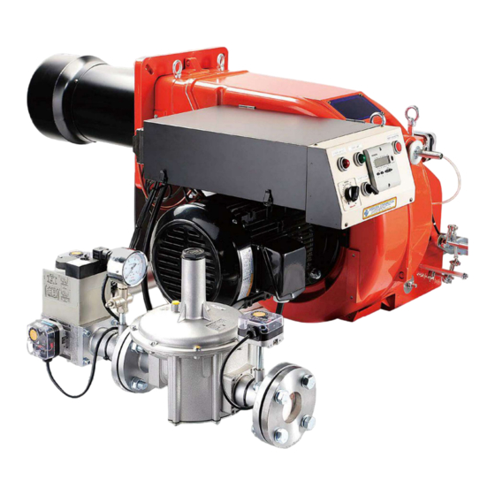
Sookook Corporation PART Ⅰ : Installation Manual 1A. Product Introduction P-type is a forced mixing-type gas burner designed to burn both LNG and LPG, enabling simple installation and repair. There is no danger of backfire because it is a NOZZLE MIX TYPE in which the pressurized air and fuel gas supplied by the blower attached to the burner burn and gets mixed simultaneously in the burner's combustion head. -
Page 7: Burner Performance Curve
Because there is no strict correlation between the initial furnace pressure and normal furnace pressure, the below chart shall be used as a reference. P60M P60M Burner Output - 4% O2 (10,000*Kcal/h) [Figure 1C-A. P3M - P60M Performance Curve (60Hz)] P72M P92M P92M P72M Burner Output - 4% O2 (*10,000 Kcal/h) [Figure 1C-B. - Page 8 Sookook Corporation P13M P15M P650M P1030M P1030M P650M P15M P13M 1000 1200 Burner Output - 4% O2 (*10,000 Kcal/h) [Figure 1C-C. P13M – P1030M Performance Curve (60Hz)] P4M LX P5M LX P60M LX P60M LX P5M LX P4M LX Burner Output - 4% O2 [* 10,000 kcal/hr]...
- Page 9 Sookook Corporation P72M LX P8M LX P92M LX P92M LX P72M LX P8M LX Burner Output - 4% O2 [* 10,000 kcal/hr] [Figure 1C-E. P72M LX – P92M LX Performance Curve (60Hz)] P13M LX P15M LX P650M LX P650M LX...
-
Page 10: External Dimensions
GW 50 0 A 5 0036 0 0 36 DMV-D 512 [Figure 1D-B. P3M - P60M, P4M LX - P60M LX (Mid-Gas Pressure, Progressive High-Low / Modulating Model)] [Table 1D-A. P3M – P60M, P4M LX – P60M LX Dimension] Dimension[mm] Boiler Dimension[mm] Model 4 –... - Page 11 G AS G V2 PGSL PGLK PG SH h ttp :// www.sookook.co.kr 상해 및 감전의 우려가 있습니 다 . 설치 및 사 용전 에 사 용설 명 서의 안전 상 주 의사항 을 경 고 읽 고 지켜 주십 시오 .
-
Page 12: Parts Description
Sookook Corporation 1E. Parts Description G W 50 A5 0036 G W 50 A5 0036 [Figure 1E-A. Low-Pressure & High/Low Burner] GW 50 A5 GW 50 A5 GW 50 A5 0036 0036 0036 [Figure 1E-B. Mid-Pressure & Progressive High/Low, Modulating Burner]... -
Page 13: Burner Installation
Sookook Corporation 1F. Burner Installation Before installing the burner, review the type of gas, the calorific value (kcal/Nm3) and gas supply pressure If they do not match, set the proper gas flow with the appropriate gas pressure or the maximum flow controller of the safety shutoff valve. -
Page 14: Gas Valve Train
Sookook Corporation 1G. Gas Valve Train Gas Piping The gas supply pipe size may vary, depending on the supply conditions. That is, if the gas supply pipe is long, the pipe size shall be large to reduce the gas pressure loss caused by the pipe. Therefore, the shorter the gas supply piping, the better. In general, the gas supply pipe shall be one size larger than the burner's gas valve train pipe. -
Page 15: Burner Circuit Diagram
CN2 (DM&PAS CONNECTION PLUG) CONNECTION PLUG) EMPTY TERMINAL *3-1 28 29 30 31 31B 32 19 20 국내 BURNER MODEL : P3M~P60M T1(20sec) *T1 shouid be set under 25sec. 16 17 (PANASONIC BURNER MODEL : P50~P250) 9 10 하 갈... - Page 16 Sookook Corporation Ver. 2 GAS BURNER CIRCUIT DIAGRAM FOR BOILER (PRO-HI/LOW) PR (MF2 R) 12(5) P PAS START 4(410) (QRA2) STOP (FLAME ROD) CRTV 10(96) CN3 BP2b 2(16) 11(3) PGSL PGLK 3(311) 2(F) PGSH PBLK 2(F) LTU 13 13 RD...
- Page 17 Sookook Corporation Ver. 9 LR (UK-BLC2) PR (MF2 R) P PAS 12(5) START 205 204 203 202 201 4(410) 220V FEED BACK (QRA2) (FLAME ROD) STOP SIGNAL OPEN (H) 4-20mA CRTV CLOSE (L) (0-135 ohm) 10(96) CN3 BP2b 2(16) 10 11...
-
Page 18: Part 2 : Operation
Sookook Corporation PART Ⅱ : OPERATION MANUAL 2A. Preparation for Commissioning Air Purge (Gas Purge in Gas Piping) Initially, the gas piping contains air, so the air purge (gas purge) is required to fill the pipeline with gas before the ignition. The air purge is the responsibility of the city gas company or plumbing contractor, but if it is not confirmed, a user shall conduct the air purge before operating the burner. - Page 19 Sookook Corporation 2B. Check Pressure Switch [Figure 2B-A. Air/Gas Pressure Switch] Air Pressure Switch (PAS) Settings This device stops the burner when the fan is malfunctioning and the combustion air is not sufficiently in-flowed. Because the ignition operation is conducted in the LOW position for the HIGH/LOW burner or proportional control burner, the air pressure switch setting shall also be made in the LOW position.
- Page 20 Sookook Corporation Gas Governor Setting If the gas supply pressure is over 3.3kPa (330mmH2O) or in the case of severe gas pressure fluctuations, a gas governor is installed to supply the gas with a constant pressure to the burner. In this case, it is necessary to correctly adjust the gas pressure suitable for the gas usage.
-
Page 21: Damper Motor Setting
Sookook Corporation 2C. Damper Motor Setting This device enables the load operation automatically when the burner is running. The shaft of this motor is connected to the air damper and gas butterfly valve through linkage device for simultaneous operation. Damper Motor of HIGH/LOW Control Burner Description SQN 30.111... -
Page 22: Commissioning Adjustment
Sookook Corporation 2D. Commissioning Adjustment Conduct the commissioning according to the followings. a) Make sure the manual shutoff valve is open. b) Check that the gas supply pressure is correct. c) If the burner does not start even after the burner operation switch is turned on, check that the burner controller is not locked out (Red light, 2E, See burner controller). - Page 23 Sookook Corporation Malfunctions after Start-up and the Causes Lockout without flame generation after “Safe Shutdown Time at Start-up” following the pre-purge - Poor air pressure (air pressure switch set pressure error or insufficient air flow) - Ignition failure (ignition transformer failure or electrode gap error) Lockout with flame generation after “Safe Shutdown Time at Start-up”...
-
Page 24: Burner Controller
Sookook Corporation 2E. Burner Controller MF2R Status Indicator & Reset Button [Figure 2E-A. MF2R Controller] Sequence Chart ON/OFF Sequence Chart Normal Operation Non Ignition Gas Pressure Switch Fan Motor Air Pressure Switch Ignition Transformer 1s 3s 1s 1s 3s Gas Solenoid Valve >30s Pre-Purge... - Page 25 Sookook Corporation MF2R LED INDICATOR CHANGE STATUS Description REMARKS Detect 5 seconds after Pressure Error Lockout starting the motor Extraneous “Flame detection before light during Lockout operation of gas valve and 적 적 startup ignition transformer” Flame detection failure for 3...
- Page 26 Sookook Corporation 2F. Gas Flow Control Gas Solenoid Valve Install a safety shutoff valve (solenoid valve) to safely supply and shut off gas to the burner. The solenoid valve that can adjust the opening of the valve can adjust the maximum flow rate of gas at the identical gas pressure. In case of HIGH / LOW burners, the maximum flow rate can be adjusted without major adjustment of the butterfly valve.
- Page 27 Sookook Corporation Gas Butterfly Valve A gas butterfly valve is installed which is connected via a damper motor and a device. The gas butterfly valve regulates the amount of gas when controlling load. How to Adjust Gas Flow of HIGH / LOW Control Burner - Gas flow control at low combustion mode The low combustion mode has small ignition angle α...
-
Page 28: Combustion Air Flow Control
Sookook Corporation 2G. Combustion Air Flow Control Air Damper An air damper is installed near the inlet to properly inflow the combustion air suitable for consumption during load operation, and it works in conjunction with a damper motor and a linkage device. - Page 29 Sookook Corporation Combustion Head Adjustment The burner is equipped with a combustion head adjuster to change the combustion condition and flame length according to the boiler type. The maximum air flow changes depending on the position of the combustion head.
-
Page 30: Part 3 : Maintenance
Sookook Corporation PART Ⅲ : Maintenance 3A. Troubleshooting Guide If any trouble occurs, first check the basic operation method. Check the electrical circuits. Check that the gas supply pressure is proper. Check whether all control devices are properly set up. -
Page 31: Regular Checkup List
Sookook Corporation 3B. Regular Checkup List The burner has a rotating part and needs to be checked regularly. If a strange noise is heard when the motor starts, the bearing is faulty and shall be replaced. If foreign matter enters the air pressure switch connection hose, the pressure cannot be delivered well. Thus, it shall be checked before operation when it is used after a long time. -
Page 32: Combustion Head Inspection And Replacement
Sookook Corporation 3C. Combustion Head Inspection and Replacement Positioning Method of Ignition Electrode - Do not connect the cable of the ignition electrode and flame rod interchangeably. - Keep the electrode well in the center to prevent metal parts from touching. -
Page 33: Storage And Installation Site Condition
Sookook Corporation 3D. Storage and Installation Site Condition Storage - Store the burner in a clean, dry and well-ventilated place with no vibration and temperature change. - Humidity: Keep below 75% - Ambient temperature: 10℃ ~ 40℃ (50℉ ~ 104℉) - A site with air-conditioning system, please operate it to prevent the condensation. - Page 34 The Advanced Burners & Technologies Head Office & Icheon Factory 107, Wonjeok-ro 290beon-gil , Shindun-myeon, Icheon-si, Gyeonggi-do, KOREA Gwanju Factory 40, Gobul-ro 279beon-gil, Gwangju-si, Gyeonggi-do, KOREA Homepage : www.sookook.co.kr Ver. 1.1 – 2022.01...
Need help?
Do you have a question about the P3M and is the answer not in the manual?
Questions and answers