Advertisement
Advertisement
Table of Contents

Related Manuals for NOH PIANIST


Summary of Contents for NOH PIANIST
- Page 1 PIANIST - Build Guide V1.1...
-
Page 2: Table Of Contents
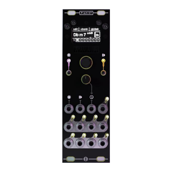
Pianist - Build Guide Introduction- This build document aims to help you with the assembly of the module. It is quite difficult to build and is not recommended as a very first build. It is highly recommended that you read through the entire guide once before starting with the assembly. -
Page 3: 2- Build Guide
Pianist - Build Guide Build Guide- • If not already mounted, start by placing the keyed header, be mindful of its orientation and match it with the indication on the PCB. • You can solder a pin on each side, check whether it sits flat on the PCB and solder the rest of the pins if it does. - Page 4 Pianist - Build Guide • On the same side, mount the 4-pins low-profile female socket for the screen • You can start by soldering only one pin, check if the socket is flat and in-line, and solder the rest if it is (or reflow if it isn’t).
- Page 5 Pianist - Build Guide • Once the male headers are inserted you can put the microcontroller board on top of both, and solder the pins • Always be extremely careful of where your soldering iron is when you solder, it should alway be oriented as far as possible from components on the board.
- Page 6 Pianist - Build Guide • Now insert the jack sockets and the white LEDs, but again- DO NOT SOLDER ANYTHING. • Watch out for the jack sockets, the middle row of jack sockets share a common pin with the row below, not above it (as shown in the picture).
- Page 7 Pianist - Build Guide • Once that is done, insert the front panel. Be mindful that nothing has been soldered in so components might fall out of place. • You can screw in the hex standoffs (as shown in the picture) to secure the panel.
- Page 8 Pianist - Build Guide • Once you have checked that no components got out of place, you can start soldering. • You can start with the potentiometer, which is in a pretty complex spot! Simply remember to have your soldering iron in an orientation that puts it as far away from other components as possible.
- Page 9 Pianist - Build Guide • The RGB LED will require more attention as the pads are closer, but the same process applies. • You can start by pushing it towards the panel, soldering only one pin, reflow to nudge it in place, and solder/clip the rest.
- Page 10 Pianist - Build Guide • You are done with the main board, congrats! You can un-tighten the four knurled nuts, and unscrew the top screws of the hex standoffs to remove the front panel from the PCB • Take the oled screen and the M2 nylon screws, nuts, and washers.
- Page 11 Pianist - Build Guide • Flip the panel, add another washer, then screw in a nylon nut to tighten the screw in place • The layers should look like what is shown on the picture, and the screw should be well-tightened.
- Page 12 • The next step only applies if your Pi Pico is BRAND NEW. Pianist DIY kits should have the firmware pre-installed.
-
Page 13: Firmware (Installation / Update)
Pianist - Build Guide Installing/Updating the Pianist Firmware • Get on the Pianist product page and download the firmware file. It should be a compressed zip file with the correct version of MicroPython (1.20.0) and another folder inside of it. -
Page 14: 4- Inspection
Module Check (debugging) - Once you are happy with all the inspection steps above, you can follow the checks detailed below to be sure that the Pianist will operate normally: • Start by giving power to the module. The expected behaviour is for the gate LED to shine a Blue/White colour and for the clock to run. - Page 15 Blue/White, it means that the firmware could not load. • If that's the case, keep the Pianist powered and plug the Pi Pico back to the Thonny IDE, open its “main.py”, run it and see what error message it gives.
- Page 16 Pianist - Build Guide • Take a patch cable and connect it to the v/oct input of an oscillator. Test out all eight outputs individually while listening to the oscillator. • All should give a higher pitch than the one you hear when nothing is patched.
-
Page 17: 5- Conclusion
Pianist - Build Guide Conclusion - This guide went through the assembly process of the module and what to be careful of when building it. If you haven’t already, you can read the user manual to know what the power requirements are and how to operate it.
Need help?
Do you have a question about the PIANIST and is the answer not in the manual?
Questions and answers