
Related Manuals for Dinter Dinko Instruments D-95


Summary of Contents for Dinter Dinko Instruments D-95
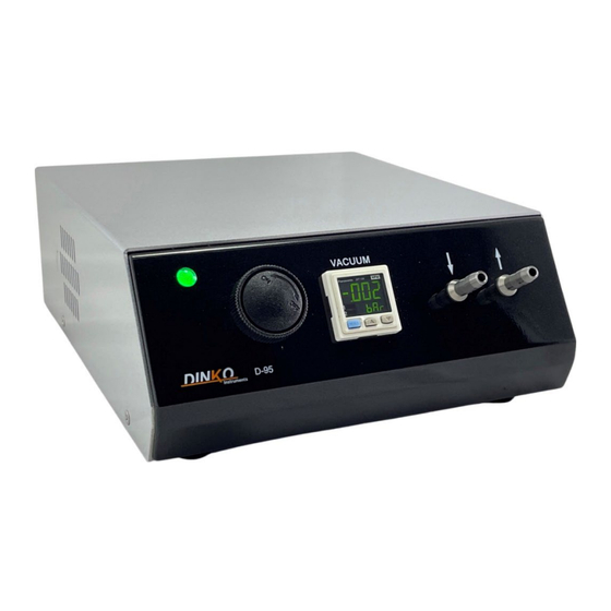
- Page 1 VACUUM PUMPS D-95 Code 1.9515.15 MANUAL May 2024 Marked c/ Encarnació , 123 -125. Tel. +34 93 284 69 62. 08024 – Barcelona Fax +34 93 210 43 07 e-mail: dinter@dinko.es www.dinko.es...
-
Page 2: Table Of Contents
INDEX Page 1- General Introduction ···································································· 3 2- Overview ···················································································· 3 Front view ·················································································· 3 Rear view ··················································································· 3 3- Packing List ················································································ 4 4- Commissioning and Control ························································· 4 5- Panasonic Digital Vacuum Controller ············································· 5 6- Factory programming ································································· 14 7- Programming ·············································································... -
Page 3: 1- General Introduction
VACUUM PUMP MODEL D-95 Code 1.9515.15 - Flow 12 L/min. Maximum vacuum -0.98 ± 2% bar - Maximum pressure 2 bar 1- GENERAL INTRODUCTION The following considerations try to guarantee a correct reception, use of the device, and the safety of the user. -
Page 4: 3- Packing List
3- PACKING LIST The Pumps are supplied complete with the following elements: Mains connection cable 110…230V AC 50/60Hz Connector for external control Silicone tube for vacuum 5x10mm, 1 meter. Manual. 4- START-UP AND CONTROL Check that the start switch (1) is in position O Connect the power cable to the equipment and to the 100…230V AC 50/60Hz power network. -
Page 5: 5- Panasonic Digital Vacuum Controller
Panasonic Digital Vacuum Controller PARTS MANUAL DP-100 pressure sensor High performance digital display DP-102 series For use outside of Japan MEUML-DP100 V1.1 Thank you very much for purchasing Panasonic Electric Works SUNX products. Co., Ltd. Please read this Instruction Manual carefully for the correct and optimal use of this product. - Page 6 NPN output type ASSEMBLY Standard Model The mounting bracket (MS-DP1-1) is optional. When the Color code of the cable with connector sensor on mounting bracket, etc. the tightening torque should be (Brown) +V less than 0.5N. (Black) Burden comparative output 1 Burden from 12 to 24V DC 100mA max.
- Page 7 Hysteresis mode Standard Model The comparative output turns ON or OFF (depending on the NO/NC configuration) when the upper threshold value is reached or setting 1 lower and remains ON or OFF until the other threshold is reached. EASY (EASY mode) Comparative output 1: OFF (OFF) Comparative output 2:...
- Page 8 setting 6 setting 4 HYS (Hysteresis Mode), or HYS (Hysteresis Mode), or Comparative output 1: Comparative output 1: WCMP (Window Comparator Mode) WCMP (Window Comparator Mode) HYS (Hysteresis Mode), or Comparative output 2: Analog voltage output / AREF (Self Reference Entry) , or WCMP (Window Comparator Mode) external input:...
- Page 9 Multifunction model ADJUSTMENT MODE <NO/NA> Adjust Description ment output mode Configure the output behavior comparative 1 comparative 1. MODE <Response time> output mode Configure the output behavior comparative 2 comparative 2. (Only in the model standard) (2.5ms) (5ms) (5000ms) analog output of Selects the analog voltage output, MODE voltage / input...
- Page 10 <Display speed> PRO MODE Adjust Description (250ms) (500ms) (1000ms) ment secondary display Select what is shown on the display MODE secondary. <Hysteresis value> • OFF: • Unit: selected pressure unit. nothing. • No.**: number. (Max.) (Min.) • CuSt: numbers, letters, signs. MODE speed of Sets the speed at which the...
- Page 11 code table Procedure for canceling the copy function 1 With the slave sensor disconnected, supply power to the sensor 2nd digit 4th digit 3rd digit teacher. 1st digit Model model only standard model standard multifunction 2 Press for approx. 2sec. MODE output Selection Mode output Selection...
- Page 12 FUNCTION REMOTE ZERO ADJUSTMENT, MODELS AND REFERENCES MULTIFUNCTION MODEL DP10 The remote zero adjustment function forces the pressure value to zero when 1: low pressure type the external signal is 2: high pressure activated. The preset value is not corrected when remote adjustment is activated to type zero.
- Page 13 SPECIFICATIONS Standard Model Multifunction model Concept low pressure type high pressure low pressure type high pressure type type pressure type nanometer pressure Rated pressure range -100 to +100kPa -0.1 to +1.0MPa -100 to +100kPa -0.1 to +1.0MPa Settable pressure range -100 to +100kPa -0.1 to +1.0MPa -100 to +100kPa...
-
Page 14: 6- Factory Programming
6- FACTORY PROGRAMMING. The controller is configured at the factory with certain parameters and locked. To visualize them, do it with the pump connected and the external connector installed. To modify the values, use the ▲▼ arrows found on the front panel. Home Screen Keep the MODE... - Page 15 Press the MODE key, the controller gives us the option to change the color of the main display (see manual for options), by default as shown in the image. Press the MODE key, the controller gives us the option to change the units of measure. By default, the programmed unit is "Bars"...
-
Page 16: 7- Programming
7- PROGRAMMING The controller allows you to set two vacuum points between which the pump will maintain a vacuum. It will depend on how the get Hi and Lo parameters are set. The Hi and Lo parameters indicate: Hi = Point of lowest vacuum. Lo = Point of greatest vacuum 7.1 Vacuum Regulation-Simple mode The Controller only indicates the vacuum that is obtained. -
Page 17: Auto-Zero
7.3 Auto - Zero To adjust the zero value “0” On the back of the pump there is a connection for external control. The corresponding connector is included with the pump. To adjust the value of "0", insert the connector into the rear connection with the pump off. Next, start the pump, the motor will remain stopped, and the indicator will show a value of “0”... -
Page 18: 8- Tables
8- TABLES Data of interest on the basis of the relationship: Vacuum gauge reading = Atmospheric pressure – residual pressure The following unit equivalences can be established kgf/ mmHg InHg mmH2O 0.001 0.000001 0.000010197 0.00750062 0.000145038 0.00001 0.0002593 0.101968 1,000,000 0.001000 0.010197 7.500616... -
Page 19: 9- External Connection Operation
9- EXTERNAL CONNECTION OPERATION Using the connector supplied with the pump, it is possible to connect any system (PLC, etc.) that activates the relay control that the pump has. You can also connect a foot pedal that will operate the pump when stepped on. When connecting the pedal the pump will remain stopped. -
Page 20: 12- Power Supply
12- ELECTRICAL POWER SUPPLY 100…240V AC 50/60Hz. 1Amp fuse. 13- CHANGE OF FUSES The fuse box is part of the power base located at the rear of the pump. See Figure. Pry with a screwdriver between the central part of the fuse holder box and the upper part of the power supply base to remove the fuse holder box. -
Page 21: 15- Exploded Pumps
15- EXPLODED PUMPS... -
Page 22: 16- Anomalies
Note of interest: Disposal of waste electrical and electronic equipment by users within the European Union. This symbol on the product or on the packaging indicates that it may not be disposed of as normal household waste. You must dispose of your residual equipment by handing it over to the collection agency for the recycling of electrical and electronic equipment. -
Page 23: 17- Warranty
Any alteration of the device by the user voids the guarantee. 18- “CE” DECLARATION OF CONFORMITY DINTER SA DINKO Instruments c/ Encarnació, 123-125 / 08024 - Barcelona Declares that the items mentioned in the attached list, to which this declaration refers, comply with the essential... -
Page 24: Other Dinko Appliances
- Spectrophotometers - Temperature Controllers - Timers -TriquiVisor - Trichinoscope - Turbidimeters - Turn Dishes - Vacuum Pumps DINTER, S.A c/ Encarnació, 123-125. Tel . +34 93 284 69 62. Fax +34 93 210 43 07. 08024-Barcelona dinter@dinko.es www.dinko.es e-mail:...
Need help?
Do you have a question about the Dinko Instruments D-95 and is the answer not in the manual?
Questions and answers