Table of Contents
Advertisement
Quick Links
Advertisement
Table of Contents

Summary of Contents for Vandewiele PROTECHNA CAMSCAN 3 5203
- Page 1 Art. Nr. 14588 I-E-0700/02.24/E Installation Manual CAMSCAN 3 5203 V5.0 - February 2024 PROTECHNA Herbst GmbH & Co. KG Lilienthalstr. 9 85579 Neubiberg Germany Phone +49 (0)89 608 114-0 +49 (0)89 608 114-48 E-Mail info@protechna.de www.protechna.de...
-
Page 2: Table Of Contents
PROTECHNA Installation Manual CAMSCAN 5203 V5 Content General Introduction ............................ 4 Safety advice ........................... 5 Mechanical installation Components of the unit ......................6 General installation sequence ....................6 Positioning of the mounting frame above the yarn sheet ........12 Adjusting of the traverse height ..................13 Exact positioning of the camera and lighting .............. - Page 3 PROTECHNA Installation Manual CAMSCAN 5203 V5 Exact adjustment of the lighting ..................29 4.5.1 How to adjust the angle of reflection for direct lighting ...........29 4.5.2 Adjustment of the transmitted lighting ................32 Exact adjustment of the camera ..................39 4.6.1 Exact adjustment of camera focus and scan time ............39 4.6.2 Exact adjustment of the camera monitoring zone limits ..........40 Initial setup of an article Setup the thread count ......................42...
-
Page 4: General
PROTECHNA Installation Manual CAMSCAN 5203 V5 General Introduction Normally the surveillance device CAMSCAN series 5203 is assembled, aligned and set for the ma- terial to be controlled by the service personnel of PROTECHNA. Additional alignment after the in- stallation is not required. For exceptions, when the customer is forced to carry out alterations at the surveillance device af- ter putting it into service or when the customer wants to install the device himself, this assembly instruction is provided. -
Page 5: Safety Advice
PROTECHNA Installation Manual CAMSCAN 5203 V5 Safety advice 1.2.1 Installation by customer If customers perform their own assembly, they are responsible for professional execution that corre- sponds to the safety guidelines. Mechanical assembly must only be carried out by a skilled mechanic. Safety shoes must be worn to protect against falling parts. -
Page 6: Mechanical Installation
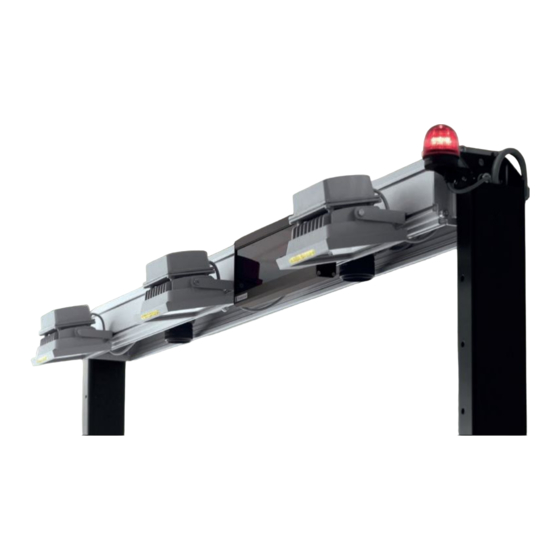
PROTECHNA Installation Manual CAMSCAN 5203 V5 Mechanical installation Components of the unit • A mounting frame, complete with holders and foot plates • Traverse containing one or more cameras (dependent on the material and the surveillance width • Lamp(s), the mounting position depends on the range to be surveilanced •... - Page 7 PROTECHNA Installation Manual CAMSCAN 5203 V5 • For CAMSCAN >50”: Use the “alternative assembly position for lamps”, see the below drawing. Fix the lamps to the lamp support (equally distributed in relation to the yarn sheet), see below drawing “Montagevarianten”. Then, install the support to the mounting frame using the con- cerning fitting sets.
-
Page 12: Positioning Of The Mounting Frame Above The Yarn Sheet
PROTECHNA Installation Manual CAMSCAN 5203 V5 Positioning of the mounting frame above the yarn sheet If the complete width of the yarn sheet is not used at the moment, please simulate this with addition- al threads. Do position the mounting frame in the middle above the maximal possible width of the yarn sheet. I.e. -
Page 13: Adjusting Of The Traverse Height
PROTECHNA Installation Manual CAMSCAN 5203 V5 Adjusting of the traverse height The height of the traverse over the yarn sheet depends on the width of the yarn sheet. Please check with the help of the following table whether the height is adjusted correctly respectively adjust the correct height. -
Page 14: Exact Positioning Of The Camera And Lighting
PROTECHNA Installation Manual CAMSCAN 5203 V5 Exact positioning of the camera and lighting The positioning of the cameras and the lighting depends on the path of the yarn sheet in the sur- veillance area. The positioning is decisive for the later adjustment of the optimal glancing angle between the camera and the material being controlled. -
Page 15: Exact Positioning Of The Additional Reed
PROTECHNA Installation Manual CAMSCAN 5203 V5 Exact positioning of the additional reed For the optimum performance of the CAMSCAN surveillance device it is necessary to mount an addi- tional reed with yarn guide rods in the immediate proximity of the surveillance area. This reed can be mounted to the side frame of the installation. -
Page 16: Electrical Installation
PROTECHNA Installation Manual CAMSCAN 5203 V5 Electrical installation Electric connection of the components The wiring and mounting positions of a 2 Camera standard installation is shown below by • way of example. Facing the production flow from the front, the control unit is mounted on the right side... -
Page 17: Electric Connection Of The Control Unit
PROTECHNA Installation Manual CAMSCAN 5203 V5 Electric connection of the control unit The electrical connection must only be carried out by suitably qualified technical personnel. Before electrical connection, you must make absolutely sure that there is no danger to come into contact with any parts that might carry live electricity. To establish the electrical connection, it is necessary to remove the top cov- er of the control unit. -
Page 18: Control Unit: Mains Connection (Standard Connection)
PROTECHNA Installation Manual CAMSCAN 5203 V5 3.2.1 Control unit: Mains connection 110-240V (standard connection) The electrical connection must be carried out by suitable quali- fied technical personnel only ! PT is the abbreviation for Protechna Power supply (Mains) PT- power cable colours 7x0.75 mm Protective earth Yellow/green Power supply (Phase) Mains... - Page 19 PROTECHNA Installation Manual CAMSCAN 5203 V5 Power supply Please connect the control unit at the terminals L (phase) and N (neutral) to an alternating power supply between 100 V and 240 V and a frequency of 50 Hz to 60 Hz. The PE terminal must be connected to the ground connection of the machine‘s switch box.
-
Page 20: Control Unit: Low Voltage Connector X2 (Optional Connections)
PROTECHNA Installation Manual CAMSCAN 5203 V5 3.2.2 Control unit: Low voltage connector X2 (optional connections) PT is the abbreviation for Protechna Stop Semiconductor output PT- Run/Reset cable colours 4x0.34 mm EARTH Earth Shield Semiconductor output (-) Yellow (if semiconductor output is configured) Semiconductor output (+) Green (if semiconductor output is configured) Stop contact (Low voltage ) -
Page 21: Control Unit: Low Voltage Connector X3 (Not Used)
PROTECHNA Installation Manual CAMSCAN 5203 V5 3.2.3 Control unit: Low voltage connector X3 (not used) This connector is not used by the CAMSCAN-Application, no connections are required. Standard connection : impulse signals from PT sensor PT is the abbreviation for Protechna Impulse signal (production cycle) PT–... - Page 22 PROTECHNA Installation Manual CAMSCAN 5203 V5 These connections are not required for a standard machine connection. Stop contact (Semiconductor output) The terminals OC+ (plus) and OC- (minus) should be connected with the electronic stopping device of the machine. They serve to provide a potential-free semi conductor output with the following data: U = 30 V DC, = 0,25 A, NO contact.
-
Page 23: Initial Operation
PROTECHNA Installation Manual CAMSCAN 5203 V5 Initial operation Prerequisites Before starting with the adjustment of the cameras, please check again the following points: The device must be assembled completely The device must be connected electrically The cameras have to be in the middle of the zone to be controlled The reed with the yarn guide rods must be assembled The yarn sheet must be inserted completely No cross-over threads or doubles may be present in the yarn sheet... -
Page 24: Preadjustment Of The Camera Focus Using The Control Unit
PROTECHNA Installation Manual CAMSCAN 5203 V5 Preadjustment of the camera focus using the control unit To adjust the camera, for example to zone 1, please proceed as follows: Remove the optics cover from the camera. Please remove only the optics cover and do not re- •... - Page 25 PROTECHNA Installation Manual CAMSCAN 5203 V5 Enter the password “85521” using the Number keys. • Confirm the password with the Enter key, then- press Home to return to the • main screen. Press the Menu key to proceed to the article set up menu. •...
- Page 26 PROTECHNA Installation Manual CAMSCAN 5203 V5 Press the Service key to enter the service screen. • Depending on the focus setting of the camera your signal may look similar to the • following picture. S 34 • Focus the camera by moving the focus ring until the thread signal is at the opti- mum.
-
Page 27: Exact Adjustment Of The Camera Monitoring Area
PROTECHNA Installation Manual CAMSCAN 5203 V5 Exact adjustment of the camera monitoring area (standard mounting) Place an approximate 2 cm wide piece of white paper after the reed onto the yarn sheet below • the camera traverse. Top View Standard installation for 2 Cameras Traverse Monitoring area 2cm paper... - Page 28 PROTECHNA Installation Manual CAMSCAN 5203 V5 Camera monitoring area without marking paper before adjustment. S 550 Adjustment of the camera monitoring area reaching the edge of the 2cm wide marking paper . S 21 Adjust camera 2 (C2) with the help of the camera tilt screw, so that the inside edge of the •...
-
Page 29: Exact Adjustment Of The Lighting
PROTECHNA Installation Manual CAMSCAN 5203 V5 Exact adjustment of the lighting 4.5.1 For direct and fluorescent lighting --> adjust the angle of reflection Remove the white marking paper. • Optimize the angle of reflection by altering the lighting device horizontally (see the following •... - Page 30 PROTECHNA Installation Manual CAMSCAN 5203 V5 To optimise the angle of reflection move the lamps in these directions Yarn sheet Correct Wrong With an inclined yarn sheet the angle of reflection must be set accordingly: • To optimise the angle of reflection move the lamps in these directions Yarn sheet...
- Page 31 PROTECHNA Installation Manual CAMSCAN 5203 V5 Before the adjustment of the lighting S 203 After the adjustment of the lighting S 410...
-
Page 32: Adjustment Of The Transmitted Lighting
4.5.2 Adjustment of the transmitted lighting Remove the white marking paper. • The distance between the top edge of the transmitted lighting and the yarn sheet has to be • greater than 30 cm. This makes sure that the lighting is outside the focus of the camera. The greater the distance, the less likely it is that interference due to dust etc. - Page 33 Distances of transmitted light illuminator(s) to filament coulter for 21"-84" systems: Top edge of crossbar / 50'' system Top edge of crossbar / 21'' system Oberkante Quertraverse / 21"-Anlage Oberkante Quertraverse / 50"-Anlage max. 1580 Filament coulter width Fadenscharbreite Filament coulter width max.
- Page 34 Top edge of crossbar / 75'' system Filament coulter width 2xDL-180-DC mounted offset -distance from filament coulter to diffuser approx. 550mm -projection of the illumination from the stand base on each side max. approx. 100 mm ! -distance of filament coulter to diffuser could also be set >55cm, then the lightings protrudes on each side max.
- Page 35 Top edge of crossbar / 75'' system Top edge of crossbar / 84'' system Filament coulter width 2xDL-180-DC mounted offset -When the lights are mounted flush with the side panels, the distance from the thread coulter to the diffuser is approx. 300. -Distance max.
- Page 36 Mounting in combination with Duo-Warpstop: 21"-Anlage Duo-Warpstop 21‘‘-system Duo-Warpstop Adapter plate camera Mounting bracket DL-Duo...
- Page 37 Set scan time and threshold: Lighting signal between set 10V and 11V with machine running 10V-11V thread signal • Set the scan time to >5ms (typ. 9ms can be set if the illumination distributor BV-537ACDC-3 has been modified to "reduced light output", recognizable by the type plate BV-537ACDC-3-C), the camera should then be centered on the diffuser width.
- Page 38 Example: Trial line at BST-Safty Textiles „Illumination signal“ max. 11 V Thread signal Thread signal in the middle of the filament coulter (white threads 350detex) Thread signal at the edge of the filament coulter white threads black threads white threads (350detex) (470detex) (350detex)
-
Page 39: Exact Adjustment Of The Camera
PROTECHNA Installation Manual CAMSCAN 5203 V5 Exact adjustment of the camera 4.6.1 Exact adjustment of camera focus and scan time Readjust the focus of the camera to achieve an optimal image of the thread signals. To do this, • set the sharpness value in the camera service display (see figure below, here “S 550”) to the maximum. -
Page 40: Exact Adjustment Of The Camera Monitoring Zone Limits
PROTECHNA Installation Manual CAMSCAN 5203 V5 • Change the scan time by pressing the + / - keys or by pressing the Pencil key. Con- firm the input by using the Enter key. To check the thread signal, return to the ser- vice screen using the Service key. - Page 41 PROTECHNA Installation Manual CAMSCAN 5203 V5 Open the service screen for camera 1 and move the left camera limit (L1) with the • two Cursor (L2) keys. S 410 To fine-tune the limit press the Zoom key for the left limit (L3) and move the limit to the •...
-
Page 42: Initial Setup Of An Article
PROTECHNA Installation Manual CAMSCAN 5203 V5 Initial setup of an article Setup the thread count To start the system it is finally necessary to input the target thread count of the complete system (in case of two zones the sum of both zones). Enter the main screen and press the Pencil key to input the target thread count. - Page 43 PROTECHNA Installation Manual CAMSCAN 5203 V5 For your notes...
-
Page 44: Additional Information
PROTECHNA Installation Manual CAMSCAN 5203 V5 Additional information Further possibilities to optimize the thread signals FOR SPECIALLY TRAINED STAFF ONLY ! Altering the aperture of the camera You have the possibility to alter the setting of the aperture (normal setting 4). Please open the aper- ture when the thread signals are too low (maximum 2,6) or close the aperture when the thread sig- nals are too high (minimal 5,8). -
Page 45: Software Update
PROTECHNA Installation Manual CAMSCAN 5203 V5 Software update The software update is made via a prepared USB-stick which includes the following files. The • control unit has to be updated first followed by the update of the DSP-Box. Essential files on the USB stick: FlashWriter.hex Basic Loading file E.g.: Camscan3.hex... -
Page 46: Software Update Of The Dsp-Box(Es)
PROTECHNA Installation Manual CAMSCAN 5203 V5 6.2.2 Software update of the DSP-Box You need to update the DSP-Box with the corresponding software version, too. Connect the USB-stick to the Service port on the rear side of the device and turn on the •... - Page 47 PROTECHNA Installation Manual CAMSCAN 5203 V5 Press the SET key to start the software update process for the DSP-Box. • After reaching 100%, the update-file was loaded on the DSP-Box succesfully. Switch off the control unit and remove the USB-stick. •...
-
Page 48: User Interface Basics
PROTECHNA Installation Manual CAMSCAN 5203 V5 User interface basics The control unit 5203 allows the complete control and parameterisation of the camera system. The relevant input pages are illustrated and described below. Meaning of the keys Softkeys (1): The meaning of the keys is described on the screen. Menu keys (2): The meaning of the keys is described on the screen. -
Page 49: Technical Data Of Main Components
Technical Data of Main Components Article Description Technical Data Weight Number [kg] 10989 Ground connection Length 40cm, for M6/ 0.032 band M6 screws 10802 Machine connection 7 x 0.75mm , outer di- 0.1 / m cable ameter 8.3mm, length 20m, 13610 Warning lamp 4180 Cable length 10m... - Page 50 Article Description Technical Data Weight Number [kg] Direct lighting 5480 24 V DC 14811 Length 558 mm 15.5 W, 1674 lm 0.34 14812 Length 1158 mm 32.0 W, 3474 lm 0.68 14813 Length 1758 mm 48.5 W, 5274 lm 1.10 14814 Power supply for di- Input: 100 - 305 V AC...
Need help?
Do you have a question about the PROTECHNA CAMSCAN 3 5203 and is the answer not in the manual?
Questions and answers