
Summary of Contents for Yada YDS60-80
- Page 1 NO: S22130038-01 YDS60-80 Smart Power Sensor G u a n g d o n g Y a d a E l e c t r o n i c s C o . , L t d...
- Page 2 Hazards and warnings Before installing, operating, or maintaining this equipment, read this manual carefully, or familiarize the equipment.This document is not an operating manual for untrained persons, and it is not responsible for problems arising outside of its normal use. Danger of electric shock, combustion, or explosion ...
-
Page 3: Table Of Contents
catalogue Chapter 1: Product Introduction ............................1 1.1 Overview ................................... 1 1.2 Function introduction..............................1 Chapter 2: Installation ................................2 2.1 Installation, prevention and preparation ........................2 2 2 Installation information .............................2 2.2.1 Installation environment and location ......................2 2.2.2 Installation dimensions ..........................3 2.2.3 Installation method ............................3 2.2.4 Wiring drawing...............................3 2.2.5 Terminal Definition ............................6... -
Page 4: Chapter 1: Product Introduction
Chapter 1: Product Introduction 1.1 Overview Smart Power Sensor is used to realize power grid power rationing and energy storage charge and discharge control. It is the core component of household energy management. RS485 wired communication can complete power measurement and power metering functions, and respond to real-time data query of the upper host. -
Page 5: Chapter 2: Installation
Chapter 2: Installation 2.1 Installation, prevention and preparation Read it before starting the operation This chapter contains important safety prevention information that must be followed before installation, service, or maintenance of electrical equipment.Read carefully and follow the following safety precautions instructions. Electric shock, the danger of burning or explosion, so only qualified operators can install the equipment.This work should be carried out after reading all the guidance.All power connections shall be disconnected before installation, inspection, testing, or maintenance.Please follow the wiring instructions in the instructions, and carefully check whether the wiring is correct after receiving. -
Page 6: Installation Dimensions
2.2.2 Installation dimensions unit:mm Tolerance: Overall dimension: length, width and height of 100 ± 0.5mm × 72 ± 0.5mm × 80 ± 0.5mm do not include wiring terminals; guide rail card slot width is 35mm.5 Weight: approximately 0.35kg 2.2.3 Installation method Installation of 35mm standard DIN guide rail;... - Page 7 Three-phase four-wire connection Three-phase three-wire connection 2) Connection Through Current Transformer and Potential Transformer (Current ≥ 0 A, Line Voltage > 500 V)
- Page 8 Three-phase four-wire connection...
-
Page 9: Terminal Definition
Three-phase three-wire connection 2.2.5 Terminal Definition joggle explain I n U a Phase A voltage incoming interface I n U b Phase B voltage incoming interface I n U c Phase C voltage incoming interface I n U n N phase voltage incoming interface O UTU a Phase A voltage outlet interface O UTU b... -
Page 10: Preparing Cables
greater than 500 V, connect the meter through potential transformers. 2 、 Input current: When the input current is 0 A to 80 A, connect the meter directly (channel 1). When the input current is greater than or equal to 80 A, connect the meter through current transformers (channel 2). 2.2.6 Preparing Cables Conductor Cross-s... -
Page 11: Display
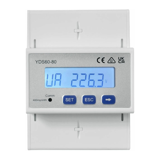
Electric pulse lamp 3.2 Display The button → is used to switch the displays. Set parameter disp to enable the rotation display function. -
Page 13: Parameter Settings
3.3 Parameter Settings 3.4 Parameter Setting Operations Button description: SET means "confirm" or "cursor move" (when inputting numbers or parameters), ESC means "exit", and → means "add". The default user password is 701. (1) Set wiring mode (three-phase four-wire or three-phase three-wire) and channel switchover (direct connection or current transformer connection):... - Page 14 (2) Set the current transformation ratio or potential transformation ratio: (3)Set communication address or baud rate: (4)Modify user password:...
-
Page 15: Definition Of The Led Indicator Lamp
3.5 Definition of the LED indicator lamp One L ED indicator on the meter panel represents the active power pulse indicator.The pulse lamp is fixed to a pulse constant of 400imp/kWh, either through or through a transformer . Chapter 4: Technical Index 4 .1 Measurement accuracy parameter accuracy... -
Page 16: Voltage And Current Input
dissipation 4.3 Voltage and current input Voltage input Overvoltage category Ⅲ Rated voltage: Loss per phase: <0.5VA 3 × 230/400 3~ Frequency 50/60H MAINS supply voltage fluctuations ± 10% Overload: 1.4 times rated voltage, continuous operation; 2 times rated voltage, Measuring range: AC30V~265V allowed 1s Measurent category... - Page 17 not tested. RS485 communication port protection level: surge differential mode 4KV (internal SURGE (surge resistance), impact resistance 42 Ω , 1.2 / 50us); RS485 communication port surge to AC power supply current port 6KV; (485 signal line connected together to AC input line and verified together) Power outlet: 6KV;...
-
Page 18: Chapter 5: Maintenance And Troubleshooting
Chapter 5: Maintenance and Troubleshooting 5.1 Troubleshooting Possible problem Possible cause Possible solutions The indicator light is not on Power supply was not added Check if the correct operating voltage is added on the after the power is on to the device equipment terminal Check whether the voltage signal is correctly connected to the device... - Page 19 Address: Gaopu Gang Yada Industrial Park, Heyuan City, Guangdong Province Domestic business: 86-762-3493871 3493872 3493873 Foreign business: 86-762-3496222 Technical support: 86-762-3493926 3493989 (400-830-0868) Fax: 86-762-3493912 3493830 Postcode: 517000 http : //www.yada.com.cn E-mail : market@yada.com.cn All rights reserved, all rights reserved.Contents are subject to change without prior notice.
Need help?
Do you have a question about the YDS60-80 and is the answer not in the manual?
Questions and answers