Table of Contents
Advertisement
Quick Links
Mounting instructions BG Display
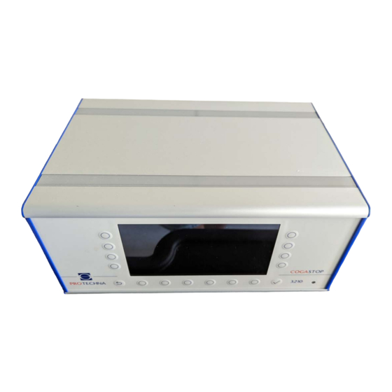
COGASTOP
TENSOSCAN
ARRAYCAM
for warp knitting and warping machines
Phone
Fax
Email
Internet
PROTECHNA Herbst GmbH & Co. KG
Lilienthalstr. 9
85579 Neubiberg
Germany
+49 (0)89 608 114-0
+49 (0)89 608 114-48
info@protechna.de
www.protechna.de
Mounting instructions BG Display V1 deutsch
3210
5374
5420
Advertisement
Table of Contents

Related Manuals for Vandewiele PROTECHNA COGASTOP 3210

Summary of Contents for Vandewiele PROTECHNA COGASTOP 3210
- Page 1 Mounting instructions BG Display V1 deutsch Mounting instructions BG Display COGASTOP 3210 TENSOSCAN 5374 ARRAYCAM 5420 for warp knitting and warping machines PROTECHNA Herbst GmbH & Co. KG Lilienthalstr. 9 85579 Neubiberg Germany Phone +49 (0)89 608 114-0 +49 (0)89 608 114-48 Email info@protechna.de Internet...
- Page 3 Copyright This manual is protected by copyright. All rights reserved. This document must not be copied, reproduced, minimised or translated in any form, neither partly nor entirely, using neither mechanical nor electronic means, without obtaining prior consent in writing from PROTECHNA Herbst GmbH &...
-
Page 4: Table Of Contents
Inhalt Safety instructions Demounting the display One control unit for different systems Demounting the housing shape cover Unplugging the grounding cable Disconnecting the flat ribbon cable Demounting the display Mounting the display Mounting the display Connecting the flat ribbon cable Connecting the grounding cable Mounting the housing shape cover Notes... -
Page 5: Safety Instructions
Safety instructions • Always follow all warnings and information that is attached to the device itself or included in this manual. • This device is sensitive to electrostatic discharge, which may cause damage to the interior of the device or affect its normal operation. Please observe the required precautions when handling components liable to damage through electrostatic discharge. -
Page 6: Demounting The Display
Demounting the display One control unit for different systems The control unit serves as an operating element for the following systems: • Cogastop 3210 • Tensoscan 5374 • Arraycam 5420 Demounting the housing shape cover Loosen the three upper screws (13438) (2) of the side panel left (14063) and the three upper screws (13438) (4) of the side panel right (14062) of the control unit. -
Page 7: Unplugging The Grounding Cable
Unplugging the grounding cable Remove the grounding cable (1) from the display (15122) (2). Disconnecting the flat ribbon cable In this step, the flat ribbon cable of the display (15122) (1) must be unplugged. To do this, the locking mechanism of the flat connector (2) must be opened. Then the flat ribbon cable (1) can be carefully pulled vertically out of the connector (2). -
Page 8: Demounting The Display
Demounting the display Loosen the four lock nuts (11547) (1) from the display (15122) (2). The display (15122) (2) can then be removed. -
Page 9: Mounting The Display
Mounting the display Mounting the display Remove the new display (15122) (2) from the packaging. Fix the display (15122) (2) with the four lock nuts (11547) (1). -
Page 10: Connecting The Flat Ribbon Cable
Connecting the flat ribbon cable Next, the flat ribbon cable of the display (15122) (1) must be plugged in. If necessary, open the locking mechanism of the flat connector. Then the flat ribbon cable (1) can be carefully inserted vertically into the connector (2). The locking mechanism must then be closed. Connecting the grounding cable Connect the grounding cable (1) to the display (15122) (2). -
Page 11: Mounting The Housing Shape Cover
Mounting the housing shape cover Place the housing shape cover (13461) (1) on the control unit. Then fix the housing shape cover (13461) (1) with three screws (13438) (2) to the side panel left (14063) and with three screws (13438) (4) to the side panel right (14062). Attention: middle screw is with a contact washer M3 (11618) (3). -
Page 12: Notes
Notes...
Need help?
Do you have a question about the PROTECHNA COGASTOP 3210 and is the answer not in the manual?
Questions and answers