Table of Contents

Summary of Contents for Oneida Air Systems SAZ100001
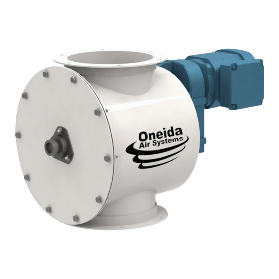
- Page 1 Owner’s Manual 10" Direct Drive Rotary Air Lock Valve 220V/460V Single/Three Phase #SAZ100001 #SAZ100000C #SAZ100460 #SAZ100600 Replacement Air Lock Seals #AXA100000 Appearance may vary slightly Rev: B 20240515LL Doc. #ZBM000035...
-
Page 3: Table Of Contents
Table of Contents System Start-Up Information System Specifications System Dimensions System Contents Rotary Air Lock System Contents Seal Replacement Assembly Instructions Maintenance Troubleshooting & F.A.Q. Recommended Accessories Warranty Information oneida-air.com... -
Page 4: System Start-Up Information
13. ENSURE enough air volume is at the suction point to capture all the particulate generated. 14. NEVER make modifications without prior approval from Oneida Air Systems. Modifying the dust collector or using it differently than intended will void the warranty and may result in malfunction or mechanical failure that leads to serious personal injury or death! DO NOT allow use as a toy. - Page 5 system start-up Information (Continued) for wind, seismic zone, and other load conditions. Codes may regulate acceptable locations for installing dust collectors. Consult with the appropriate authorities having jurisdiction to ensure compliance with all national and local codes regarding dust collector installation.
- Page 6 Oneida Air Systems assumes no responsibility or liability for the suitability of any fire and/ or explosion mitigation strategy, or any items incorporated into a collector as part of an owner/operators hazard mitigation strategy.
- Page 7 system start-up Information (Continued) can produce concentrations of dust well into the combustible range. 15. ALWAYS check that all dust collection equipment is properly selected and sized for the intended use. Authorities with jurisdiction should be consulted before installing to verify local codes and installation procedures. In the absence of such codes, install collector according to the National Electric Code, NFPA No.
-
Page 8: System Specifications
On/Off Switch Magnetic Starter with Overload Protection SySTEM DIMEnSIOnS AnD COnSTRUC TIOn Primary Build Materials Cold Rolled Steel with a powder-coated finish Inlet 10" ID Flange Discharge 10" ID Flange Overall Height 19" Overall Weight 110 lbs Oneida Air Systems, Inc. -
Page 9: System Dimensions
system Dimensions Nominal dimensions shown. Dimensions subject to slight variations in manufacturing. Select a position for the Air Lock allowing for 16" of clearance for installation and maintenance access. 13" 330 mm 11-3/4" 300 mm 10-1/4" 262 mm 7/16" Ø 11 mm 26-1/4"... -
Page 10: System Contents Rotary Air Lock
**For the Three Phase Air Locks (SAZ100000C, SAZ100460, and SAZ100600) Components can be found inside the Motor. you will need the following tools: ROTARy AIR LOCk 7/16" Wrench 1/2" Socket Wrench 7/16" Socket Wrench 9/16" Wrench 1/2" Wrench 9/16" Socket Wrench Oneida Air Systems, Inc. - Page 11 system Contents rotary air lock (Continued) Reset STOP Exploded 96 NC 98 NO 97 NO oneida-air.com...
-
Page 12: System Contents Seal Replacement
Please unpack the parts carefully and confirm you have received each item listed here. you will need the following tools: ROTARy AIR LOCk 7/16" Wrench 1/2" Socket Wrench 1/8" Allen Wrench 7/16" Socket Wrench 9/16" Wrench Phillips Head Screw Driver 1/2" Wrench 9/16" Socket Wrench 1/4" Drift Punch Oneida Air Systems, Inc. - Page 13 system Contents seal replacement (Continued) oneida-air.com...
-
Page 14: Assembly Instructions
On the Air Lock Assembly (A) make sure the end of the Rotor Shaft (A2A) is clean and free of damage [FIG. 2]. Note: Dirt or burrs can cause the Rotor Shaft (A2A) to jam and make it difficult to remove. FIG. 2 Oneida Air Systems, Inc. - Page 15 assembly Instructions (Continued) For Three Phase Air Locks, remove the plastic cap found on the side of the Motor (B). Set aside the 1/4" Key (B1) and Anti-Seizing Coating (B2) found inside the Motor (B); Discard the bolt and washer. [FIG. 3A] For Single Phase Air Locks, the 1/4"...
- Page 16 1” deep and then gently rotate the Motor clockwise until the top rib aligns with the left side of the torque tab on the Main Body (A1). Finish pushing the Motor onto the Rotor Shaft FIG. 6a [FIG. 6B]. FIG. 6b Oneida Air Systems, Inc.
- Page 17 assembly Instructions (Continued) Secure the Motor (B) to the Air Lock Assembly (A) using the hardware set aside from Step 1; One 3/8"-16 x 1-1/4”" Hex Head Bolt (A1D), two 5/16" Flat Washers (A1E), and one 3/8"-16 Nylock Nut (A1F) and tighten fully [FIG.
- Page 18 Assembly’s (A) top flange to the bottom of Collector your dust collector’s cyclone separator. Secure with twelve 3/8"-16 x 1" Hex Head Bolts (E), twenty-four 3/8" Flat Washers (F), and twelve 3/8" Nylock Nuts (G). Tighten fully [FIG. 10]. FIG. 10 Oneida Air Systems, Inc.
- Page 19 assembly Instructions (Continued) WIRE ACCORDIng TO ALL AppLICAbLE CODES. IMpROpER WIRIng CAn CAUSE ELECTROCUTIOn OR FIRE. THE MOTOR MUST bE pROpERLy gROUnDED. DEpEnDIng On HOW WIRED, THE AIR LOCk MAy START AUTOMATICALLy. AIRLOCk MUST HAvE ELECTRICAL OvERLOAD pROTECTIOn SEpARATE FROM THE MOTOR OF THE ...
- Page 20 EEC 1-1.6A Overload FLA Dial Wiring to Motor U1, U2 - White V1, V2 - Brown Air Lock Motor W1, W2 - Yellow U3 - Black V3 - Red W3 - Blue Motor Ground FIG. 12 Oneida Air Systems, Inc.
- Page 21 assembly Instructions (Continued) WIRE ACCORDIng TO ALL AppLICAbLE CODES. IMpROpER WIRIng CAn CAUSE ELECTROCUTIOn OR FIRE. THE MOTOR MUST bE pROpERLy gROUnDED. DEpEnDIng On HOW WIRED, THE AIR LOCk MAy START AUTOMATICALLy. AIRLOCk MUST HAvE ELECTRICAL OvERLOAD pROTECTIOn SEpARATE FROM THE MOTOR OF THE ...
- Page 22 0.56-0.8A Overload FLA Dial 96NC 98NO 97NO 95NC Wiring to Motor U1 - Brown V1 - White Air Lock Motor W1 - Yellow U2 - Red V2 - Black W2 - Blue Motor Ground FIG. 14 Oneida Air Systems, Inc.
-
Page 23: Maintenance
Maintenance UnpLUg yOUR UnIT bEFORE SERvICIng OR CLEAnIng. LOCk OUT / TAg OUT THE MOTOR'S pOWER SUppLy. DAngER! ROTOR TURnS WITH SUFFICIEnT FORCE TO CAUSE SEvERE InjURy. Replacement Air Lock Seals Remove the ten 5/16"-18 x 1" Hex Head Bolts (A5), twenty 5/16"... - Page 24 Shaft and keep the hardware loose at this time. Refer to the Assembly Instructions (see page 12) to finish reassembling the Air Lock. Tighten bearing set screws with 1/8" allen wrench. Tighten Oneida Air Systems, Inc.
-
Page 25: Troubleshooting & F.a
What dust can be collected? Oneida Air Systems' dust collectors are designed and tested for wood and wood dust. They can and have been used effectively for various other dusts and chips, such as drywall dust, paper dust, agricultural dust, metal chips and other forms of debris. -
Page 26: Recommended Accessories
• Assembly is made quick and easy thanks to the convenient Snap-Lock seam running down the length of the pipe. Auxiliary Start/Stop Station #AMP000001 • Industrial push button control box provides additional control locations for your dust collection system. • Can be daisy chained together to position controllers through the shop. Oneida Air Systems, Inc. -
Page 27: Warranty Information
In no event shall Oneida Air Systems’ liability under this warranty exceed the purchase price paid for the product and any legal actions brought against Oneida Air Systems shall be tried in the State of New York, County of Onondaga. - Page 28 Regardless of where you purchased your system, if you have any questions or issues with missing / damaged parts, please call Oneida Air Systems first to let us help resolve your problem. We fully stand behind the quality of our product and place the utmost value satisfaction of our customers.
Need help?
Do you have a question about the SAZ100001 and is the answer not in the manual?
Questions and answers