Table of Contents
Advertisement
Quick Links
Advertisement
Table of Contents

Summary of Contents for Lilee Systems STS-1020
- Page 1 STS-1020 On-Board Installation Guide...
- Page 2 Copyright Copyright © 2022 LILEE Systems, Ltd. LILEE Systems, TransAir, and the LILEE Systems logo are trademarks of LILEE Systems. All other brands, products, or service names are or may be trademarks or service marks of their respective owners. Name: STS-1020 On-Board Installation Guide...
-
Page 3: Table Of Contents
Connect the terminal blocks Power cable pre-check Connecting power to the STS unit Power on/off delay Antenna Installation Antenna position guidelines Examples of good antenna placement Installing LTE and GPS antennas Set torque of connectors STS-1020 On-Board Installation Guide Contents | 3... - Page 4 Mounting the STS and Meraki Units Mounting the STS unit Connecting and mounting the Meraki access point Completing the installation Configuration Set cloud or local management Setting STS position Cellular firmware Checking firmware version Upgrading cellular firmware Update the preferred roaming list (Sprint, Verizon) Front Panel Ports and Indicators Maintenance port Console port...
- Page 5 Other maintenance STS-1020 On-Board Installation Guide Contents | 5...
-
Page 6: Pre-Installation
"Rear Panel Connectors and Indicators" on page 55 "Maintenance" on page 62 This guide focuses strongly on the STS-1020 hardware but also includes some references to sim- ilar STS-1010 hardware. If you are not using the STS-1010, you can simply ignore references to it. -
Page 7: Package Contents
Tray-mounted 2.5” 32 GB SSD (SATA0), shipped in accessory box Console cable (RJ-45 to DB9) Six M3 Phillips flat head screws, to mount optional drive at SATA1 (STS-1020) Contact support if any of these items are damaged or missing. STS-1020 On-Board Installation Guide... -
Page 8: Tools And Materials
Ring terminals (Qty. 1) Butt splices (Qty. 2) Caution: LILEE Systems requires 14/3 AWG wire when connecting power using ations that use the digital I/O port for power on/off delay. Current on this wire is 8 | Tools and materials... -
Page 9: Determining Sts Position
You will need to know your position's reference number after installation, during software configuration of the unit. Note: Physically, this means that there are 24 possible positions. LILEE Systems yet officially tested and supported, please discuss with your LILEE Systems sup-... -
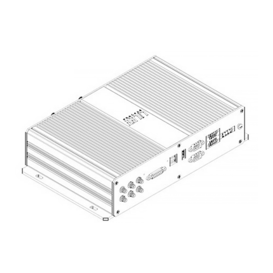
Page 10: Identifying Faces Of The Sts Unit
Identifying faces of the STS unit Face Description Name Face that features Ethernet switch ports, status lights, SIM card slots, and STS model number at Front top left corner. The top is up when the front is facing you with its text upright. It is the largest face that features cooling fins. -
Page 11: Specifications
This chapter lists mechanical, operating environment, and electrical specifications for the STS platform. Mechanical Weight: 6.61 lbs. (3 kg) Dimensions (H x W x L): 2.6 x 7.1 x 11.7 in (67 x 181 x 298 mm STS-1020 On-Board Installation Guide Specifications | 11... -
Page 12: Operating Environment
Operating environment Functional operating temperature: -40 to 158 °F (-40 to 70 °C) Safe operating temperature: -40 to 122 °F (-40 to 50 °C) Storage temperature: -67 to 185 °F (-55 to 85 °C) Ambient relative humidity: 5 to 95% non-condensing Electrical Connector: 4-pin terminal block, male pin Input voltage: 10 to 30 VDC (2 ms minimum ramp up time is recommended) -
Page 13: Power
12/2 AWG or 14/2 AWG. When those images were created, a separate ground Choose power connection type When connecting power to the STS-1020, the first and most important decision you must make is what type of power connection you want to use. This will affect the rest of your installation. -
Page 14: Soft Power On/Off
A qualified vehicle electrician or mechanic should choose the circuit. Prepare wiring The STS-1020 uses 14/3 tinned marine wire for its power run and a single conductor of 18 or 20 AWG tinned marine wire for the optional digital I/O connection. -
Page 15: Digital I/O
Follow these steps to prepare the terminal block for power at the STS end of the power cable: 1. Locate the 4-pin terminal block in the accessory box, and loosen screws 1 and 3 at the bottom of the block. STS-1020 On-Board Installation Guide Digital I/O | 15... - Page 16 2. At the STS end of the power cable, connect the black wire to pin 1 (-) and the red wire to pin 3 (+) of the 4-pin terminal block. 3. Tighten the set screws on bottom of the terminal block to secure the wires in place. 4.
-
Page 17: Power Cable Pre-Check
Hold the cables together in one hand, and the 4-pin terminal block in the other. Pull your hands away from each other, then push them together to test the cables. Repeat once or twice. They should remain secure. STS-1020 On-Board Installation Guide Power cable pre-check | 17... -
Page 18: Connecting Power To The Sts Unit
Connecting power to the STS unit The following steps explain how to connect power to the STS units. Please review the following warnings and read the entire section before you begin. 10–30 VDC. Doing so can cause fire and/or an electrical shock. Warning: Always remove power from the DC circuit before performing any elec- Warning: To power the unit on, follow all electrical safety guidelines. - Page 19 Place the STS approximately 6 inches from the front side (closest to the front of the bus) of the over- head bin, with the front panel facing you and the bus walkway/aisle. STS-1020 On-Board Installation Guide Connecting power to the STS unit | 19...
- Page 20 Step 2: Cable positioning Place the power cable behind the STS in the overhead bin, to check positioning. Do not connect yet. To ensure proper placement of the STS in relation to the Meraki AP, position the Meraki AP approx- imately 2 to 3 feet away from the STS (towards the rear of the bus) in the overhead bin, with the front panel facing you and the bus walkway/aisle.
- Page 21 Connect the red power wire clamp to the positive (+) terminal of the bus' power. Optional, not pictured: Connect your separate true ignition wire to your chosen true ignition cir- cuit. STS-1020 On-Board Installation Guide Connecting power to the STS unit | 21...
- Page 22 Step 5: Connect power to STS Screw the green block connector on the STS power cable into the DC IN port on the rear panel of the STS. Optional true ignition wire, not pictured: In the same manner, connect the 5-pin terminal block to the digital I/O port, immediately to left of the PWR port.
- Page 23 If the LEDs do not light, check all your connections (red, black, and white) and verify that they are good. If all connections look good and the LED lights are still not on, contact LILEE Systems. Step 7: Verify power off Turn the bus ignition off.
-
Page 24: Power On/Off Delay
Power on/off delay The STS does not start up or shut down immediately. The power on/off delay feature is used for install- ations in vehicles. The delay in starting up allows time for the engine to start, so the STS is not drawing on the battery when the vehicle is starting. -
Page 25: Antenna Installation
Antennas going into two different modems/dialers that are using the same carrier would need to be mounted on the different side of the bus. Any deviation from this guideline is not allowed without discussion and agreement from the rest of the CIM team. STS-1020 On-Board Installation Guide Antenna Installation | 25... -
Page 26: Examples Of Good Antenna Placement
Examples of good antenna placement The following images illustrate antenna placement which complies with guidelines. Example 1 (two carriers) Carrier A: Antennas A0 and A1 Carrier B: Antennas B0 and B1 GPS: C0 26 | Examples of good antenna placement... - Page 27 Example 2 (two carriers) Carrier A: Antennas A0 and A1 Carrier B: Antennas B0 and B1 GPS: C0 (dashboard) STS-1020 On-Board Installation Guide Examples of good antenna placement | 27...
-
Page 28: Installing Lte And Gps Antennas
Installing LTE and GPS antennas Step 1: Tape LTE antennas Apply three strips of double-sided adhesive tape to the back of each LTE antenna. You must apply the tape in an " " formation, as shown here: 28 | Installing LTE and GPS antennas... - Page 29 For the GPS antenna, apply a square of Velcro tape to the backside of the antenna, like this: Step 3: Labeling Use sharpie pens and electrical tape to number each antenna and its plug end. STS-1020 On-Board Installation Guide Installing LTE and GPS antennas | 29...
- Page 30 Step 4: Cable routing Before attaching anything to the bus, route the antenna cables from the STS unit to the antenna loc- ations to ensure proper placement. Once you have verified the route, secure the cables such that they will not be disturbed or moved in transit. Do not attach the anntennas yet. When routing, use the following diagram as a guide for placement: 30 | Installing LTE and GPS antennas...
- Page 31 Using the numerical labels that you added to each antenna/plug, do a final placement check prior to attachment. Once you're sure each antenna is in the correct place, remove the adhesive backing from the double- backed tape and attach to the pre-selected locations. STS-1020 On-Board Installation Guide Installing LTE and GPS antennas | 31...
-
Page 32: Set Torque Of Connectors
Step 6: Attach antennas to posts By hand, fasten the LTE 0, LTE 1, and GPS antennas securely onto the front of the STS, connecting each numbered antenna to its corresponding post as shown. (use diagram on step 2 and step 4). Set torque of connectors After connecting all antennas (LTE, GPS, and Wi-Fi) to the STS, use an SMA 5/16 (3.5 mm) torque wrench. -
Page 33: Mounting The Sts And Meraki Units
STS. Before touch- ing components, or connecting or disconnecting cables, touch a metal object to dis- Caution: Ensure that the power cord is disconnected whenever you service, STS-1020 On-Board Installation Guide Mounting the STS and Meraki Units | 33... -
Page 34: Mounting The Sts Unit
Mounting the STS unit Step 1 Verify that the front panel of the STS is facing you and the bus walkway/aisle. 34 | Mounting the STS unit... - Page 35 Mount the base of the STS in the overhead bin using four of the #8-32 x ¾ in. long self-piercing screws and the Phillips screwdriver. Mount only the STS in place; do not use these screws to mount cable ties or anything else. STS-1020 On-Board Installation Guide Mounting the STS unit | 35...
-
Page 36: Connecting And Mounting The Meraki Access Point
Connecting and mounting the Meraki access point Step 1 Slide the Meraki AP off the mounting plate before attaching the plate to the overhead bin. 36 | Connecting and mounting the Meraki access point... - Page 37 Step 2 Mount the Meraki AP installation plate using two of the #8-32 x ¾ in. long self-piercing screws and the Phillips screwdriver. STS-1020 On-Board Installation Guide Connecting and mounting the Meraki access point | 37...
- Page 38 Step 3 Connect one end of the RJ45 Cat-6 Ethernet cable (3 ft.) to the bottom side of the Meraki AP, and the other end to the PoE Port 0 on the front panel of the STS. 38 | Connecting and mounting the Meraki access point...
-
Page 39: Completing The Installation
Use the set screw provided with the Meraki AP to fasten the unit in place. Completing the installation Step 1 Turn on the bus. Step 2 Complete the post-Installation Checklist to verify that the system is working properly. STS-1020 On-Board Installation Guide Completing the installation | 39... -
Page 40: Configuration
Set cloud or local management Starting with LileeOS 4, STS hardware will default to using the LILEE Systems T-Cloud platform for man- agement. If you plan to manage a unit locally instead of via T-Cloud, you must disable centralized man- agement during hardware onboarding to achieve local mangement of the a unit. -
Page 41: Cellular Firmware
SIM is correctly installed. READY Step 2: Download the latest carrier firmware from the Lilee Systems FTP site. Put it in a location access- ible from the STS via FTP, TFTP, or HTTP. (HTTP is recommended.) Warning: Warning: Do not upgrade directly from the LILEE Systems FTP site, as Step 3: Log in to the LileeOS command line on the STS. -
Page 42: Upgrading Cellular Firmware
Step 1: Log in to the LileeOS command line on the STS. Step 2: Enter the following command: update interface cellular <interface-number_0_or_1> image <path_to_firmware> For example: STS-1020 > update interface cellular 0 image http://10.2.10.21/SWI9X30C_02.30.03.00_ Generic_002.046_001.zip % Total % Received % Xferd... - Page 43 <interface-number_0_or_1> firmware-list For example: STS-1020 > show interface cellular 0 firmware-list Index | Carrier ID | Folder ID | Storage Type | Pri Image ID | Pri Image Build ID | FW Image Build ID | Active --------------------------------------------------------------------------------------------------------------- 002.027_000...
-
Page 44: Update The Preferred Roaming List (Sprint, Verizon)
At time of installation, you should manually trigger the update as a one-time pro- cedure. This does not apply when using other carriers. To update the PRL, execute this command as root: STS-1020 > update interface cellular<index> preferred-roaming-list 44 | Update the preferred roaming list (Sprint, Verizon) -
Page 45: Front Panel Ports And Indicators
The following table lists the proper settings for connecting to the STS console port. Setting Value Baud Rate 115200 Data Bits Parity None Stop Bits Flow Control None STS-1020 On-Board Installation Guide Front Panel Ports and Indicators | 45... -
Page 46: Gigabit Ethernet Ports
SIM card bay The STS-1020 has a bay for four 2FF standard-sized (15 x 25 mm) SIM cards. The STS-1010 has a bay for two 2FF standard-sized (15 x 25 mm) SIM cards. The thickness tolerance for each SIM card is 0.71 to 0.81 mm. - Page 47 3. If a SIM card is present, press gently to release it from the spring-loaded mechanism, then remove STS-1020 On-Board Installation Guide SIM card bay | 47...
- Page 48 (do not touch the metallic contacts). You will feel resistance as the card pushes against a spring. When you hear a click, the card is installed. 5. Optional: When using two SIM cards with an STS-1020, insert the second new SIM card in slot LTE1/0, as shown below.
- Page 49 6. Replace the dust control door and tighten its screws. The SIM installation procedure is complete. STS-1020 On-Board Installation Guide SIM card bay | 49...
-
Page 50: Led Indicators
LED indicators The following table describes behaviors for the front-panel LED indicator lights. Behavior Description No power Green Power on Amber Standby power Green LileeOS ready Amber LileeOS in sleep mode Application Engine off, or system asleep Green Application Engine enabled Green Contact Support. -
Page 51: Gps Antenna Connector
SATA SSD bays The STS-1020 has two bays for 2.5" SATA SSDs (SATA0 and SATA1). The STS-1010 has only SATA0. The included 32 GB drive (SATA0) ships in the accessory box. SATA1 ships empty, and you may contact LILEE support for information on optional SATA1 drives. - Page 52 1. Remove power from the STS. 2. Remove the SSD tray from the front of the STS by unscrewing the two socket-cap Phillips-head screws at the SATA bay. Slide the tray out, as shown below. To replace an SSD, continue to step 3. To install an SSD in bay SATA1, proceed to step 5.
- Page 53 Note: Be sure to properly orient the signal ports on the back of the HDD/SSD. These must rest at the rear of the HDD tray to ensure proper connection to signal interfaces. STS-1020 On-Board Installation Guide SATA SSD bays | 53...
- Page 54 6. Slide the SSD tray back into the SATA bay and secure it to the STS by replacing the two socket-cap Phillips-head screws previously removed. The SSD installation procedure is now complete. 54 | SATA SSD bays...
-
Page 55: Rear Panel Connectors And Indicators
Solid green 3 to 10 seconds Reset to factory defaults and reboot. Blinking green Reset to factory defaults and reboot with the Greater than 10 seconds Solid green minimum configuration. STS-1020 On-Board Installation Guide Rear Panel Connectors and Indicators | 55... -
Page 56: Obd-Ii/J1939 Connector
OBD-II/J1939 connector The STS has a female DB15 serial port for an OBD-II/J1939 connector. Contact sup- port@lileesystems.com to obtain information on how to purchase an OBD-II or J1939 cable that is appropriate for your vehicle. This table lists the pins and their descriptions: Description CAN1 High(+) —... -
Page 57: Hdmi Port
HDMI port The STS has an HDMI connector for attaching a monitor. The HDMI connector supports brand name HDMI cables. The Philips SWV5401H version 1.4 cable was used during testing. STS-1020 On-Board Installation Guide HDMI port | 57... -
Page 58: Com Ports
COM ports The STS has two COM ports, COM 0 and COM 1, with male DB-9 connectors for direct local management. To facilitate the COM port mode switching, the termination resistor used for accurate RS-422/RS-485 communication is integrated into the STS system. No termination resistor is required when the COM port is configured to RS-422/RS- 485 full-duplex or RS-485 half-duplex mode. -
Page 59: Digital I/O Pin Definitions
Digital output 1 1001 Ground Digital input 3 1003 Digital input 1 1001 Ground Digital output 0 1000 Ground Digital input 2 1002 Tr.lg. True Ignition (TRIG) digital input 0 1000 STS-1020 On-Board Installation Guide Digital I/O pin definitions | 59... -
Page 60: Digital Inputs
Digital inputs All digital inputs use a photo coupler. Current between 0.5 mA and 10 mA activates the coupler. Details for the digital input are: High voltage: 5 – 30 VDC @ 0.5 mA minimum, 10 mA sinking maximum Low voltage: < 0.8 VDC This figure describes the digital input circuit: 60 | Digital inputs... -
Page 61: Digital Outputs
Current limit: 3.5 A (for short protection) This figure describes the digital output circuit: Ground receptacle The STS has a ground receptacle with nut and lock-washer. See "Connecting power to the STS unit" on page 18. STS-1020 On-Board Installation Guide Digital outputs | 61... -
Page 62: Maintenance
CR2032 cells sourced by LILEE Systems may carry CAUTION: Risk of Explosion if Battery is replaced by an Incorrect Type. Dispose of Used Batteries According to the Instructions. - Page 63 There are no user-serviceable parts inside the chassis. If any significant amount of dust, water, or fluid enters the STS, immediately disconnect power and con- tact your distributor or sales representative. STS-1020 On-Board Installation Guide Other maintenance | 63...
- Page 64 LILEE Systems (Headquarters) LILEE Systems (Asia Pacific) 91 E Tasman Dr 16 Xinzhan Rd Ste 24F, Banqiao District San Jose, CA 95134 New Taipei City, Taiwan 220...
Need help?
Do you have a question about the STS-1020 and is the answer not in the manual?
Questions and answers