Table of Contents
Advertisement
Quick Links
Information and specifi cations in the manual were in effect at time
of printing of this manual. ECR International reserves the right to
discontinue, change specifi cations or system design at any time
without notice and without incurring any obligation, whatsoever.
Check our website frequently for updates: www.freewatt.com
Hydronic Control
®
Model HDJ
INSTALLATION,
OPERATION AND
MAINTENANCE MANUAL
Module,
P/N# 240008295, Rev. B [1/2011]
www.ecrinternational.com
Advertisement
Table of Contents

Summary of Contents for ECR freewatt HDJ
- Page 1 MAINTENANCE MANUAL Information and specifi cations in the manual were in effect at time of printing of this manual. ECR International reserves the right to discontinue, change specifi cations or system design at any time without notice and without incurring any obligation, whatsoever.
-
Page 2: Table Of Contents
• Honda MCHP Model MCHP 1.2D & DP Installation Manual and Owner’s Manual • HAI Thermostat Owner’s Manual • Applicable ECR Zone Control Manual • freewatt Transfer Switch installation, Operation and DANGER Maintenance Manual Indicates a hazardous situation which, if not avoided, •... -
Page 3: Introduction
Control Module Functions freewatt PLUS System. • Control module integrates boiler and Honda MCHP with There are different ECR zone pump/valve relay controls communicating thermostat, outdoor temperature sensor required for use with pump and valve-zoned systems and remote monitoring capability. - Page 4 (including the priority domestic hot will result in hot water scalding hazard. water and Smart Zone) are needed. Additional ECR zone controls may be required and • System Will Function Without Internet Connection: Full installed accordingly.
-
Page 5: Installation
Figure 3-2 Mounting wide x 4 ft. high sheet of plywood for control module, ECR relay switches and HI Module. HI module may be mounted up to 20 feet away from Honda MCHP unit. Locate enclosure with installation and service accessibility in mind. - Page 6 (2-pole; 15 amp recommended) as required by code; • High Voltage Wiring Route 120 VAC wiring from switch to ECR controls and to control module; Terminate 120 VAC wiring with wire nuts inside control module as shown in Figure 3-3;...
- Page 7 Extend Red cable from control module's PMP1 to AR822’s TR. Extend black cable from control module's PMP2 to AR822’s ECR Zone Controls: Control module connects to ECR Zone Controls (ARM-6P, AZ-6CP and ARH-3) with low voltage thermostat wire. Follow applicable electrical schematic.
-
Page 8: Initial Service Verification
4 - INITIAL SERVICE VERIFICATION 4.2 Internet Connection & Commissioning 4.1 Initial Service Verifi cation • freewatt System control module connects to Perform prior to troubleshooting: customer’s home network in same way any • Verify circuit breaker is ON or fuse is properly computer or other network appliance does functioning at electrical panel. -
Page 9: Sequence Of Operation
5 - SEQUENCE OF OPERATION... - Page 10 5 - SEQUENCE OF OPERATION...
-
Page 11: General Troubleshooting
6 - GENERAL TROUBLESHOOTING Hydronic freewatt PLUS System consists of eight major WARNING components: Electrical shock hazard may cause serious injury • Boiler, or death. Avoid touching live electrical contacts. • freewatt Control Module, Service shall be performed by trained, experienced •... -
Page 12: Alarm Code Section
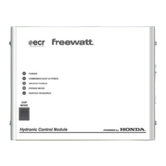
7 - ALARM CODE SECTION 7.1 Alarm Codes for Service Required LED on freewatt Control Module ERROR INDICATES CHECK OR REPAIR CODE 1. CHP MODE SWITCH IN ON POSITION 2. CABLES AND CONNECTIONS BETWEEN THE THERMOSTAT AND THE HI MODULE THERMOSTAT COMMUNICATIONS ERROR 3. -
Page 13: Control Module Fuses
8 - CONTROL MODULE FUSES 8.1 CONTROL MODULE FUSE WARNING Electrical shock hazard. Label all wires prior to • Turn OFF power to System at external line switch. disconnection when servicing controls. Wiring • Remove front panel from control module enclosure. errors can cause improper and dangerous operation. -
Page 14: Wiring Diagrams
9 - WIRING DIAGRAMS Figure 9-1 HDJ - 240 VAC Wiring Only... - Page 15 9 - WIRING DIAGRAMS Figure 9-2 HDJ - 120 VAC Wiring Only...
- Page 16 9 - WIRING DIAGRAMS 9-3 HDJ - 120 VAC Wiring - Control Module & Zone Pumps...
- Page 17 9 - WIRING DIAGRAMS 9-4 HDJ - 120 VAC Wiring - Control Module & Zone Valves...
- Page 18 9 - WIRING DIAGRAMS 9-5 HDJ - 120 VAC Wiring - Control Module & Hydro Air...
- Page 19 9 - WIRING DIAGRAMS 9-6 HDJ - Low Voltage Wiring Only...
- Page 20 9 - WIRING DIAGRAMS 9-6 HDJ - Low Voltage Only Wiring - Control Module and Zone Pumps...
- Page 21 9 - WIRING DIAGRAMS 9-7 HDJ - Low Voltage Only Wiring - Control Module & Zone Valves...
- Page 22 9 - WIRING DIAGRAMS 9-8 HDJ - Low Voltage Only Wiring - Control Module & Zone Valves with Expansion Zones...
- Page 23 9 - WIRING DIAGRAMS 9-9 HDJ - Low Voltage Only Wiring - Control Module & Hydro Air...
- Page 24 9 - WIRING DIAGRAMS 9-10 MCHP - Low Voltage Wiring...
-
Page 25: Installation Checklist
10 - INSTALLATION CHECKLIST Installation Checklist Check the following upon completion of Hydronic Control Module Installation: Inspect controller for properly secured connections Inspect hydronic pump's power cable for properly secured connections Visually inspect all fuses... -
Page 26: Installation Notes
11 - INSTALLATION NOTES... - Page 27 11 - INSTALLATION NOTES...
- Page 28 ® Check our website frequently for updates: freewatt www.ecrinternational.com www. .com Hydronic Control Module was installed and commissioned by: DATE freewatt PLUS TECHNICIAN freewatt PLUS DEALER P.O. Box 4729 Utica, NY 13504-4729 www.freewatt.com www.ecrinternational.com...
Need help?
Do you have a question about the freewatt HDJ and is the answer not in the manual?
Questions and answers