Table of Contents
Advertisement
Quick Links
Product Name
Product SKU
Product URL
Based in New York City & Toronto, GAO Tek Inc. is ranked as one of the top 10 global B2B technology suppliers. GAO ships
overnight within the U.S. & Canada & provides top-notch support thanks to its 4 decades of experience.
Wireless Transceiver
GAOTek-WM-118
https://gaotek.com/product/gaotek-wireless-
transceiver/
P a g e
| 1
Advertisement
Table of Contents

Summary of Contents for GAOTek GAOTek-WM-118
- Page 1 P a g e Product Name Wireless Transceiver Product SKU GAOTek-WM-118 Product URL https://gaotek.com/product/gaotek-wireless- transceiver/ Based in New York City & Toronto, GAO Tek Inc. is ranked as one of the top 10 global B2B technology suppliers. GAO ships overnight within the U.S. & Canada & provides top-notch support thanks to its 4 decades of experience.
-
Page 2: Table Of Contents
P a g e TABLE OF CONTENTS 1. Overview ..................Error! Bookmark not defined. 1.1. Brief Introduction ........................3 Features ............................ 3 Application ..........................4 2. Specification and parameter ......................4 Limit parameter ........................4 Operating Parameter ......................... 4 3. Size and pin definition ........................5 4. -
Page 3: Overview
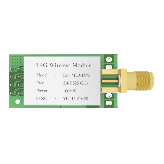
P a g e 1. Overview 1.1. Brief Introduction Wireless transceiver is a DIP module based on original imported nRF24L01P form Nordic in Norway, operates at2.4 GHz with 100mW transmitting power. The RF performance of transceiver andcomponents selection during R&D are all in accordance with industrial grade standards, using industrial-grade high- precision 16MHz crystal oscillator, also it obtained FCC, CE and RoHS certification. -
Page 4: Application
P a g e 1.3 Application Wearable device; Smart home and industrial sensors; Security system, positioning system; Wireless remote control, drone; Wireless game remote control; Healthcare products; Wireless voice, wireless headset; Automotive industry applications. Specification and parameter 2.1 Limit parameter Performance... -
Page 5: Size And Pin Definition
P a g e Main parameter Description Remark Test condition :clear and open area, antenna gain: 5dBi, Distance for reference 2500m antenna height: 2.5m,air data rate: 250kbps FIFO 32Byte Max length transmitted each time Crystal frequency 16MHz Modulation GFSK Package Connector 2.54mm Pin Communication interface... -
Page 6: Basic Operation
P a g e Pin No. Pin item Pin direction Pin application Ground Power supply must be 2.0~ 3.6V Input Chip Enable Input SPI Chip select Input SPI clock MOSI Input SPI master output slave input MISO Output SPI master input slave output Output Interrupt request. - Page 7 P a g e Assuming the module is soldered or placed over the Top Layer, it is wrong to randomly route over the Bottom Layeror other layers, which will affect the module's spurs and receiving sensitivity to varying degrees; 8. It is assumed that there are devices with large electromagnetic interference around the module that will greatly affect the performance.
-
Page 8: Software Editing
P a g e 4.2 Software editing This module is nRF24L01+PA+LNA, the drive mode is exactly equivalent to nRF24L01P, the user can operate according to the nRF24L01P manual (Please see nRF24L01P manual for more details). As interrupt pin for IRQ, it can be used to wake-up MCU and achieve fast response; ... -
Page 9: Basic Application
P a g e 4. Basic application 5.1 Basic circuit diagram 6.1 Communication range is too short The communication distance will be affected when obstacle exists. Data lose rate will be affected by temperature, humidity and co-channel interfere ... -
Page 10: Module Is Easy To Damage
P a g e | 10 voltage, the lower the transmitting power. Due to antenna quality or poor matching between antenna and module. Module is easy to damage Please check the power supply source, ensure it is 2.0V~3.6V, voltage higher than 3.6V will damage the module. -
Page 11: E01 Series
P a g e | 11 E01 Series Test Frequency Tx power Model No. distance Package Antenna E01- nRF24L01 2.4G IPEX ML01IPX E01- nRF24L01 2.4G ML01DP4 E01- nRF24L01 2.4G SMA-K ML01DP5 E01- nRF24L01 PCB/IPE 2.4G ML01SP2 E01- nRF24L01 2.4G IPEX ML01SP4 E01- nRF24L01... -
Page 12: Packing
P a g e | 12 Packing 10.1 Anti-statistic pallet Based in New York City & Toronto, GAO Tek Inc. is ranked as one of the top 10 global B2B technology suppliers. GAO ships overnight within the U.S. & Canada & provides top-notch support thanks to its 4 decades of experience. - Page 13 | 13 Contact us: sales@gaotek.com Based in New York City & Toronto, GAO Tek Inc. is ranked as one of the top 10 global B2B technology suppliers. GAO ships overnight within the U.S. & Canada & provides top-notch support thanks to its 4...
Need help?
Do you have a question about the GAOTek-WM-118 and is the answer not in the manual?
Questions and answers