Advertisement
Quick Links
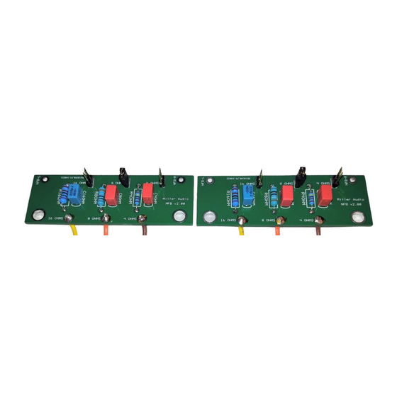
Photo 1: Prototype NFS PCB's, ready to install into a Dyna-70 / -120 Ultimate Amplifier
Parts Supplied:
2- PCB's for Left & Right Channels
6- Header Pins (kit includes extra parts, these are easily damaged with too much heat)
2- Jumper Links (only one is used per PCB; it goes on the desired impedance Header Pin)
2- 680 pF/400V 5% Film Caps
2- 470 pF/400V 5% Film Caps
2- 220 pF/400V 5% Film Caps
2- 2.4K Ohm 1% Resistors
2- 3.9K Ohm 1% Resistors
2- 7.5K Ohm 1% Resistors
6 inches each of 18 ga. stranded wire in Yellow (16-Ohm), Orange (8-Ohm) & Brown (4-Ohm)
2- 8/32 Standoffs
Before starting assembly, we recommend:
That you inspect the kit and ensure you have all parts listed above;
You read this Kit Assembly and Installation Manual 3-4 times to ensure you understand and
can follow the assembly and installation steps as presented;
You install the smallest, shortest, or lowest height parts first, followed by larger / taller parts
last.
You have access to the original Dynaco ST-70 Assembly Manual.
WARNING!
Be sure to prevent any solder or wire debris from falling into the open Output
Transformer openings within the chassis, ref. Photo 2 below. If any solder, metal particles or
pieces of wire fall into the transformer, you must remove the Transformer and clean it out to
prevent the possibility of a short in your Output Transformer. Use some duct tape, a small rag cloth
stuffed into the openings, etc. to keep anything from falling into the transformer! Remember this
warning, you will read it again !
Negative Feedback Selector (NFS)
Kit Assembly & Installation Manual
for Dyna-70 & Dyna-120 Amplifiers
Advertisement

Summary of Contents for Miller Audio NFS
- Page 1 Negative Feedback Selector (NFS) Kit Assembly & Installation Manual for Dyna-70 & Dyna-120 Amplifiers Photo 1: Prototype NFS PCB’s, ready to install into a Dyna-70 / -120 Ultimate Amplifier Parts Supplied: 2- PCB’s for Left & Right Channels 6- Header Pins (kit includes extra parts, these are easily damaged with too much heat) 2- Jumper Links (only one is used per PCB;...
- Page 2 PCB, as depicted in the first page photo, Photo 1. Photo 3- Unpopulated NFS PCB showing component location & RC values B. PCB Component Installation 4. Refer to Photo 3 above for component locations & values; install the 3 resistors in their respective locations;...
- Page 3 You can remove and discard these parts; they are no longer needed since they have been moved to the NFS PCB and the NFS kit includes the new parts that are re-located to the NFS PCB. Use solder wick and/or a solder sucker to remove all solder as well as the 4 components.
- Page 4 Note: The doubling of the leads on the speaker output terminals can be a bit “fiddly” and it can be difficult to keep both the transformer output wires and the NFS wires attached simultaneously while soldering. We wrap the 3 NFS wires around & over the Transformer...
- Page 5 8/32 screw to hold PCB in Place. This single fastener mount is usually all it takes to mount the NFS PCB. Ensure that there are no live contacts on the bottom of the NFS PCB touching the chassis (or anything else). You can use some double stick foam tape to isolate the bottom of the PCB if so inclined.
Need help?
Do you have a question about the NFS and is the answer not in the manual?
Questions and answers