Table of Contents
Advertisement
Quick Links
Advertisement
Table of Contents

Summary of Contents for JPL Stevie 1
- Page 1 Single-Phase, In-Wall Installation Guide Models: Stevie 1 & Stevie 1D...
-
Page 2: Power Cable Entry - Method
This guide is for information purposes only, it is provided as is, and may be subject to change without notice. JPL EV Ltd does not accept liability for the correctness or completeness of the information or illustrations supplied. For the most up-to-date Installation Guide go to our website www.steviechargers.com. -
Page 3: Installation Details
Installation Details To be completed by the Installer: Date of installation: Address of property where Stevie has been installed: Serial number of installed unit: ___ ___ ___ ___ ___ ___ ___ ___ ___ ___ ___ ___ ___ (Found on the main case under the front fascia cover, back of this guide, and on the label on the outside of the packaging) Installer Contact Details: Name of installer: Installer’s mobile telephone number:... -
Page 4: Declaration Of Conformity
Hereby declare that the products listed below to which this declaration relates, are in conformity with the essential requirements of the Low Voltage Directive 2014/35/EU. JPL EV Code: Stevie 1 - IWS, Stevie 1D - IWS The following standards and technical specifications have been applied:... -
Page 5: Table Of Contents
In-Wall Installation Product Information Name Card Support and Contacts Commissioning and Maintenance Before Installation Connecting WiFi via the JPL EV Installer App Safety Instructions Smart Charging via the Monta App/Portal In-Wall Box Contents LCD Displays Stevie 1 - Key Features... -
Page 6: Important Information
See page 31. Declaration of Conformity Full testing and inspection of the new installation according to the JPL EV Limited declares: This product latest wiring regulations must be carried out before Stevie is used to complies with the basic health, safety and charge a vehicle. -
Page 7: Introduction
Introduction Thank you for choosing Stevie® for your EV Charge Point. Our U.K. design team have carefully designed and crafted the Stevie® EV charge point, which at the time of launch is unique in this market, offering “On-Wall or In-Wall” mounting options. We want you to be proud of choosing Stevie®. -
Page 8: Product Information
This guide can be subject to change at anytime without notice. Stevie is a registered trademark of JPL EV Ltd. Stevie products are protected by patent. Single-Phase, In-Wall Installation Guide... -
Page 9: Before Installation
A combined RCD and overcurrent protection device In-wall (RCBO), according to EN 61009-1, is typically the preferred Stevie Charge Point choice recommended by JPL EV Ltd for a safe, user-friendly and cost efficient installation. Considerations RCDs must disconnect all live conductors. -
Page 10: Safety Instructions
Safety Instructions Important note: Please read this booklet before installing and switching on this appliance. The manufacturer assumes no responsibility for incorrect installation and usage as described in this booklet. Keep the installation guide for future reference. All the information in the guide is valid for the EV charge point model in this manual. This installation guide details the installation guidance for the charger. -
Page 11: In-Wall Box Contents
What comes in the Box Metal Cage Main Case Pearl White Fascia Galvanised steel sleeve for recessed in-wall Toughened plastic box housing UV shielded front cover protects the installation. electrical components. electronics from the elements. Comprising 2 parts: front & back shells. Installation fixings 4 x Wall Plugs 4 x Screws... -
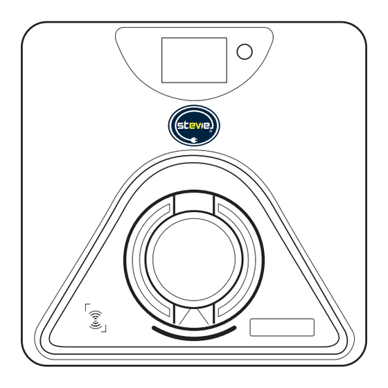
Page 12: Stevie 1 - Key Features
Stevie 1 - Key Features Single-Phase, In-Wall Installation Guide... - Page 13 Stevie 1 - Key Features 1. Touch Sensitive Button: Activates the local interface and illuminates the LCD display screen, charging socket down light and personalisation window. 2. LED Display Screen: Charging status notifications displayed to echo status shown on smart phone App.
-
Page 14: Location Of Components - Socketed Unit
Location of Components Single-Phase, In-Wall Installation Guide... - Page 15 Socketed Unit Please read and digest before starting your 10. Load balance terminal installation 11. Type B RCD * Stevie installations must only be carried out by 12. CP (and PP) terminal a qualified electrician registered to a competent person scheme. All installation work, for safety & 13.
-
Page 16: Mounting The Charger
In-Wall Installation - Brick Cavity Stage 1 Preparation for installation into a brick cavity wall: Stevie has been designed to easily fit into a brick cavity wall. Using standard London Brick sizes, a hole can be cut (or left open if a new construction) in the size of 1 brick wide and 3 bricks high, using the mortar line as a guide. An allowance has been made for slight variations in brick size and installation. - Page 17 In-Wall Installation - Other Wall Types Stage 1 Preparation for installation into other wall types: Stevie has been designed to not only be installed into brick cavity walls, but other construction types too. The same metal cage is used for these installations. For concrete block type walls: 1.
-
Page 18: Preparation For Installation
Preparation for Installation Stage 2 Removing the Fascia from the Main Case: 1. Using the plastic fascia removal tool supplied, push the tapered end into the lower slots on the bottom edge of the fascia to release clips. (Refer to fig. 2). Gently remove fascia and set to one side. - Page 19 Preparation for Installation Stage 2 Accessing the Stevie Charge Point: fig. 4 1. Using the security screwdriver bit supplied (found in the Installer kit), remove the 6 screws marked “a” and using a Phillips screwdriver, remove the single screw marked “b” from the front shell, save the screws for subsequent use.
- Page 20 In-Wall Installation - Brick Cavity Stage 3 For installation into a brick cavity wall: 1. Remove the 4 fixing screws holding the rear main case to the metal fixing cage. Save these screws for later use (see fig. 4). 2. Place the metal cage into the newly-cut hole in the brickwork (minimum height, from the ground of 0.5m and to a maximum height of 1.5m).
- Page 21 In-Wall Installation - Other Construction Stage 3 For installation into other wall construction types: 1. Remove the 4 fixing screws holding the rear main case to the metal fixing cage. Save these screws for later use (see fig. 6). 2. Place the metal fixing cage into your prepared hole in the wall (minimum height, from the ground of 0.5m and to a maximum height of 1.5m).
-
Page 22: Power Cable Entry
Power Cable Entry WARNING: Method 2 Make sure that the power source is turned off before installing the unit. Rear Entry Manufacturers and distributors are not responsible for any loss or related responsibilities caused by any incorrect installation. The installer shall be responsible for the loss and damage of the product, system or property caused by improper installation. -
Page 23: Power Cable Entry - Method
WARNING: If there is any damage caused to the Stevie unit during drilling, DO NOT continue with this installation. The Stevie unit MUST be returned to JPL EV Ltd for inspection and re-certification before re-installation of the unit. Failure to adhere to this invalidates your warranty. - Page 24 Power Cable Entry fig. 9 m Consumer Power Cable Entry Method 2 (Rear Entry - Single-phase) Wiring cap a. Cut the supply cabling wires to approx 130mm in length. Expose the cores by stripping back approx 18mm of insulation. (Please refer to cable sizing tables to calculate required supply cable size.
- Page 25 Power Cable Entry Method 2 (Rear Entry - Single-phase) e. Attach the fixing clamp and fixing plate loosely as shown in fig. 11. f. Insert the supply cable (max ø 17mm) through the fixing clamp and tighten the fixing plate to secure the cable using the 2 screws supplied as shown in fig.
-
Page 26: Ct Clamp Wiring
CT Clamp Wiring CT Clamp (Current Clamp) The CT clamp will monitor the total load (amps) going through the home. If the CT clamp detects that the load is close to exceeding the maximum the house is able to handle, then the charge rate on the charger will be reduced. Load Management Function Note: This unit must be grounded (Earthed). - Page 27 B - Black R - Red CT Clamp Wiring c. Attach the two CT wires (black and red) to the CT wire terminal (supplied in the Installer Kit) and then insert it Attach CT wires to termina into the CT interface on the Stevie unit in position CT1, fig. 14. fig.
-
Page 28: Ct Clamp Installation
CT Clamp Installation Load Management Function e. Attach 1 x CT clamp to the property mains live incoming supply cable BEFORE the electricity meter. See fig. 15 for guidance. Ensure the directional arrow on the CT clamp points towards the electricity meter. fig. -
Page 29: Load Management - Setting The Dip Switch
Load Management Setting the DIP Switch The DIP switch is factory set to provide a maximum charging current of 32A, however, you may need to set the current DIP switch according to the minimum wire size as shown in the table below. CAUTION 1: The unit must be isolated from mains power before any changes are made to the DIP switches. -
Page 30: Ethernet Network Connection
Ethernet Network Cable Ethernet Network Connection - For models with ethernet capability a. Following on from steps shown in fig. 13 on page 26. b. Pierce one of the 5 holes in the sealing rubber, insert the network cable into the sealing rubber, then insert it into the housing, as shown in fig.13. -
Page 31: In-Wall Installation
In-Wall Installation Attaching the Stevie Charge Point into the Wall: Note: Ensure all cables, (power, CT clamp, ethernet) have been fitted to the Stevie charger unit and inserted through the wall before attaching the unit securely to the wall. The power cable must NOT be connected to the mains supply yet. 1. -
Page 32: Name Card
Name Card Touch sensitive button to activate the illumination of the LCD display, charging socket and name card area. Illuminates for 60 seconds. Individual Personalisation: LED illuminated designated place for installer to insert a label with their contact details or for the home owner to add their house name or number. - Page 33 In-Wall Installation Sealing the Stevie Charge Point: 1. Ensure all cables are connected correctly and securely and are not loose or damaged. 2. Confirm the WiFi antenna is securely attached and the plug is pushed firmly into its port. 3. Attach the front shell to the back shell making sure not to trap any wires.
-
Page 34: Commissioning And Maintenance
Commissioning and Maintenance Inspection a. This unit must be grounded (Earthed). b. Switch the supply to the unit on. The unit will cycle through red, blue and green lights to self-check and enter the corresponding mode. (Allow 45-60 seconds). c. Ensure you are satisfied the installation is complete and tested as safe before leaving with the end user. d. -
Page 35: Connecting Wifi Via The Jpl Ev Installer App
Connecting WiFi via the JPL EV Installer App The following steps will guide you through the simple 12 step process for configuring the Stevie charger. Step 1: Download the Stevie Installer App. Step 2: Step 3: Load the Stevie App. - Page 36 Connecting WiFi via the JPL EV Installer App Step 4: Step 5: Step 6: Step 7: Connect to your home Wait for the Wi-Fi network Connect to your Stevie Wait for the Stevie Charger Wi-Fi network, input the to configure.
- Page 37 Connecting WiFi via the JPL EV Installer App Step 8: Step 9: Step 10: Step 11: Wait for the Stevie Charger Connect to your home Wait for the App to scan You’re Connected. to restart. Wi-Fi network. your Wi-Fi network for the Make a note of your Stevie Charger.
-
Page 38: Smart Charging Via The Monta App/Portal
Smart Charging via the Monta App/Portal Download the Monta App. https://app.monta.app/d/powered-by-monta Open the app and follow the easy step by step instructions to create an account. Default Pre-set Charging Time Exclusions Default off-peak charging set by the Monta App is from 22:00hrs to 08:00hrs and from 11:00hrs to 16:00hrs Monday to Friday. - Page 39 Step 2: Step 3: Step 4: Step 5: Select the charge point Select your charge type: Monta will apply the The charge point is now you have connected to Charge now is for quick required default delay of a charging. your electric vehicle.
- Page 40 Socketed unit ONLY: Once the charge has stopped, the cable connected to your electric vehicle must be disconnected from the car before the charge point will unlock it’s socket. (Disconnect cable from car before disconnecting from charge point). If you have enabled the cable lock function then the cable stays locked to the Stevie charge point.
-
Page 41: Lcd Displays
if not compatible show if not compatible show a full blue dial a full blue dial 06:00am 06:00am 06:00am 06:00am Dial to fade on and off. Dial to fade on and off. 56% 7 kW 56% 7 kW 56% 7 kW 56% 7 kW LCD Displays Main hub... -
Page 42: Cable Holder
Cable Holder Installation of the Cable Holder (supplied with tethered chargers only, available to purchase as an optional accessory) Wall Plugs Screw Fixing Plate M6*30 ST4.2*32 Main Body Screw Fig.21 Fig.22 Fig.23 1. Remove the single screw from the bottom of the cable holder and Fig.24 separate the fixing plate and the main body parts (see fig. -
Page 43: Installation Check List
Installation Check List Please Tick Box to confirm all checks Is the Stevie unit securely affixed to the wall? Are all cable entry points adequately tightened and seals checked? Are all cable connections secure? If fitted, is the CT clamp correctly installed (arrow facing in correct direction) and termination secure? If fitted, is the ethernet cable plug secure? Is the internal antenna plug connected and antenna securely affixed to the main case? Has a personalisation card been placed into the window? -
Page 44: Troubleshooting
Troubleshooting Fault ID Red Light Flashing Description of Fault Recommended Solution/Troubleshooting 783FID1 Three fast, one slow Power Supply Ground Fault Contact your Installer or Stevie support. Check ground wire is well connected. PEN fault protection relay open. 783FID2 Internal RCD tripped Power off Stevie at isolator switch if installed, or at supply source (MCB/RCBO etc), wait 30 seconds and switch the power back on. - Page 45 Troubleshooting Fault ID Red Light Flashing Description of Fault Recommended Solution/Troubleshooting 783FID9 Two fast, two slow Pen Fault Potential PEN fault activation, power off Stevie at isolator switch if installed, or at supply source (MCB/RCBO etc), wait 30 seconds and switch the power back on.
- Page 46 Troubleshooting Fault ID Red Light Flashing Description of Fault Recommended Solution/Troubleshooting 783FID16 Two fast, four slow Metering chip anomaly Metering chip fault. Power off Stevie at isolator switch if installed, or at supply source (MCB/RCBO etc), wait 30 seconds and switch the power back on. If fault persists, contact your installer or Stevie support.
-
Page 47: Technical Data
Technical Data Socketed Tethered Model 783-001-001, 783-004-001 Item Power Supply 1P+N+PE Input Rated Voltage AC220 ~ 240V 50/60Hz Rated current Max 32A (6-32A adjustable) Output Voltage AC220 ~ 240V 50/60Hz Rated Power 7.4kW Output Maximum Current Max 32A (6-32A adjustable) Charger socket Type 2 (IEC 62196-2) or connector... -
Page 48: Warranty
What does my warranty NOT cover? Conditions of Warranty • Misuse, abuse, negligence, acts of nature, accident, JPL EV Limited, grants 3 years Manufacturer’s Warranty disassembling or modification of, or to any part of, the from the date of purchase, as the manufacturer of this product. - Page 49 Limitation of Liability near explosive atmospheres, flammable gases and In no event will JPL EV Limited accept any liability for any blasting sites. This also includes areas where the air loss, costs or consequential damage due to the use and/ contains chemicals or dust particles (e.g.
- Page 50 3 of this guide. Todber, Sturminster Newton, Netherlands Dorset DT10 1JH. England. February 2024 - Version 1.0 Customers Service: Customers Service: © 2024 JPL EV Ltd. All rights reserved Tel: +44 (0)1258 822514 Tel: +31 35-808-0201 E&OE E-mail: sales@steviechargers.com...
Need help?
Do you have a question about the Stevie 1 and is the answer not in the manual?
Questions and answers