Table of Contents
Advertisement
Quick Links
Advertisement
Table of Contents

Related Manuals for HBK SomatXR MX Series

Summary of Contents for HBK SomatXR MX Series
- Page 1 ENGLISH Operating Manual MX Modules SomatXR Rugged DAQ www.hbm.com/start...
- Page 2 Hottinger Brüel & Kjaer GmbH Im Tiefen See 45 D-64293 Darmstadt Tel. +49 6151 803-0 Fax +49 6151 803-9100 info@hbkworld.com www.hbkworld.com Mat.: DVS: A04089 08 E00 00 11.2023 E Hottinger Brüel & Kjaer GmbH Subject to modifications. All product descriptions are for general information only.
-
Page 3: Table Of Contents
TABLE OF CONTENTS Safety Instructions ..........Markings used . - Page 4 MX1615B-R bridge module ......... 6.2.1 Pin assignment MX1615B-R .
-
Page 5: Safety Instructions
10 … 30 V The supply voltage connection as well as the signal and sense leads must be installed in such a way that electromagnetic interference does not adversely affect device functional ity (recommendation: HBK "Greenline Shielding Design", download from www.hbm.com or www.hbkworld.com). - Page 6 CX22B-R: BR2330A/FAN (soldered) Only trained and qualified personnel authorized by HBK may change batteries. General dangers of failing to follow the safety instructions The module is a state of the art device and as such is failsafe. The module may give rise to residual dangers if it is inappropriately installed and operated by untrained personnel.
- Page 7 In particular, any repair or soldering work on motherboard, or replacement of components, is prohibited. When exchanging complete modules, use only genuine parts from HBK. The module is delivered from the factory with a fixed hardware and software configuration. Changes may only be made within the options documented in the instructions.
- Page 8 The personnel operating the automation equipment must have been instructed in the handling of the machines, and be familiar with use of the modules and of the technologies described in this documentation. The commissioning engineers and service technicians must have successfully completed training that qualifies them to repair automation systems.
-
Page 9: Markings Used
MARKINGS USED Markings used in this document Important instructions for your safety are highlighted. Following these instructions is essential in order to prevent accidents and damage to property. Symbol Meaning This marking warns of an imminently threatening DANGER dangerous situation in which failure to comply with safety requirements will result in death or extremely serious physical injury. -
Page 10: Symbols On The Device
Symbols on the device Caution Indicates that care must be taken when operating the device, and the instructions in the operating manual must be followed when using the module. Warning of hot surfaces Indicates that the marked item may be hot, and should not be touched without taking precautions. - Page 11 Electrostatically sensitive components Components marked with this symbol can be damaged beyond repair by electrostatic discharge. Please observe the handling instructions for electrostatic sensitive devices. Connection to functional ground You can use this connection to integrate the module into your functional grounding, where necessary, so that interference currents are diverted and no interfering signals are fed in.
-
Page 12: Introduction
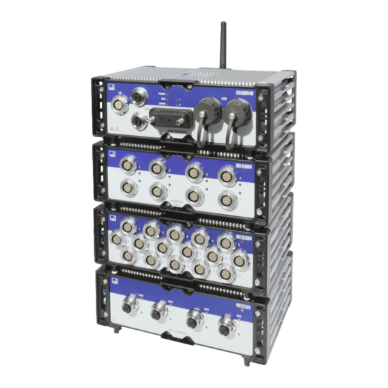
INTRODUCTION SomatXR DAQ The SomatXR series is a rugged data acquisition system of modular design that is universally applicable for measurements of any kind. The modules in this family can be combined and intelligently interconnected specific to the measurement task. Distributed operation makes it possible to position individual modules close to the measuring points, resulting in short sense leads. -
Page 13: Overview Of Modules And Transducers
The SomatXR series includes the following CX modules: CX22B-R data recorder: The CX22B-R comes with the pre-installed catman® Easy software package for test parameterization, visualization, and data analysis in the field. The acquired test data is stored on the integrated solid state drive (SSD). Information For details on the CX22B-R, refer to the separate CX22B-R operating manual. - Page 14 Transducer ● ● ● Strain gage quarter bridge, 3-wire 3-wire only 3- or 4-wire configuration ● ● Inductive full bridge ● ● Inductive half bridge ● LVDT (linear variable differential transformer) ● ● Piezoresistive transducer MX Modules INTRODUCTION...
- Page 15 Transducer ● ● Potentiometer ● ● ● ● Voltage, 60 V, 10 V, 100 mV 60 V 10 V only only ● ● ● Current-fed piezoelectric transducer (IEPE, ICP®) ● ● ● Current, 20 mA ● ● Resistance or resistance- based measure...
- Page 16 Transducer ● ● Resistance thermometer PT100 only PT100 or PT1000 ● ● Thermocouple Type K or T ● ● Frequency/ pulse counter Chan nels (timer, TTL) ● ● Incremental encoder Chan nels (timer, TTL) ● ● Torque/ rotational Chan nels speed MX Modules INTRODUCTION...
- Page 17 Transducer ● Passive inductive encoder Pulse width modulation ● Crank wheel sensor ● ● SSI protocol Chan nels ● ● ● Chan CAN bus nel 1 MX Modules INTRODUCTION...
- Page 18 Transducer ● CAN-FD bus ● Absolute pressure sensor (gas/ liquid) ● Relative pressure sensor (gas/ liquid) Use quarter bridge adapter 1-SCM-R-SG1000-2, 1-SCM-R-SG120-2 or 1-SCM-R-SG350-2. ODU 14-pin to BNC 1-KAB430-0.3 adapter can optionally be used. Adapters 1-SCM-R-TCK-2 for type K, 1-SCM-R-TCE-2 for type E, 1-SCM-R-TCT-2 for type T, and 1-SCM-R-TCJ-2 for type J.
-
Page 19: About The Documentation
About the documentation The SomatXR documentation includes: Printed Quick Start Guide. SomatXR series operating manuals in PDF format. Various data sheets for SomatXR modules and accessories. Various mounting instructions (in PDF format) for cables, adapters and connectors. Comprehensive online help and user-friendly search options available after installing the Windows PC software (e.g. - Page 20 A working standard calibration certificate is stored on each measuring amplifier, and can be read out via the MX Assistant. Autoboot (module configurations are retained) Measuring amplifiers have the following features for each channel: Galvanic isolation Signal inputs for power supply and communication Mutual signal inputs (except MX1615B-R) Configurable power supply for active sensors Support for TEDS technology (read, write)
-
Page 21: System Setup
SYSTEM SETUP A SomatXR system can be set up in various ways: MX modules connected to a host PC (explained in this manual) MX modules connected to a data recorder (SomatXR CX22B-R or QuantumX CX22B, eDAQXR CPU layer or eDAQXR-lite CPU layer) (explained in the relevant recorder manuals) MX modules connected to a gateway (SomatXR CX27C-R, QuantumX CX27B or CX27C) (explained in the relevant gateway manuals) - Page 22 1-NTX002 X104 Power supply 1-KAB294-5 1-KAB293-5 X101/X102 X100 B series: 1-KAB273-5 C series: 1-KAB2106-x For more information on connecting the module to a host PC, see section 4.4 and section 4.5. SomatXR MX modules can be used as stand-alone devices or in a network with central ized control, data synchronization and common power supply via FireWire.
-
Page 23: Mechanical Mounting Of The Modules
Mechanical mounting of the modules For information on equipment available for mounting SomatXR modules and accessories, visit www.hbm.com or www.hbkworld.com. Order No. Item Description 1-CASELINK Installation parts Four (4) elements for mechanical connection 1-CASELINK-RUG-2 Installation parts Four (4) robust elements for mechanical connection 1-CASEMOUNT Mounting brackets... -
Page 24: Caselinks (1-Caselink Or 1-Caselink-Rug-2)
1-CASELINK 1-CASELINK-RUG-2 1-CASEMOUNT 1-CASEMOUNT2-2 1-CASEMOUNT3-2 1-CASEMOUNT-UMB-2 4.2.1 Caselinks (1-CASELINK or 1-CASELINK-RUG-2) A set of caselinks consists of four (4) elements to connect two (2) SomatXR modules. Set screws (M5) are included with the mounts to secure them to the modules. 4.2.2 Casemounts (1-CASEMOUNT, 1-CASEMOUNT2-2 or 1-CASEMOUNT3-2) Use 1-CASEMOUNT to mount one module... - Page 25 Notice HBK recommends mounting modules individually in environments subject to strong vibration. Individually mounted SomatXR modules are vibration- and shock-resistant in accordance with MIL-STD-202G. Top modules of stacked configurations may exceed vibration and shock specifications in environments subject to strong vibration. Make sure that the mounted modules do not exceed the vibration and shock specifications (see module data sheets).
- Page 26 Instructions The casemounts have been pre-assembled. The mounting diagram is not to 1: 1 scale. The dimensions can be used as a guide for tapping the holes. 1. Insert a housing ring (B) into the slots on the side of a module. Install the two (2) case clips on opposite corners of the module, as shown in the mounting diagram.
-
Page 27: Universal Mount (1-Casemount-Umb-2)
3. A set of four (4) caselinks can hold two (2) stacked modules together. Kit 1-CASE MOUNT2-2 contains 1-CASELINK-RUG-2 for two (2) modules. Kit 1-CASEMOUNT3-2 contains 1-CASELINK-RUG-2 for three (3) modules. 4. First attach the mounts (F or G) to the connecting elements (CASELINK) using the M5 countersunk screws and a #2 Phillips screwdriver. - Page 28 Instructions (typical use case) Assemble the module tower completely before threadlocking the cross-head (Phillips) screws. 1. Apply a serviceable (blue) threadlocker to the four (4) M5 set screws (E) in each caselink (D). Use a 2.5 mm Allen wrench to turn the fastening screws back into the caselinks before attaching the caselinks to a module.
- Page 29 5. Axis camera and L-Com BT-CAT6P1HP-48W 6. L-Com BT-CAT6P1HP-48W and PoE Power injector power supply unit (Axis camera mounted separately) Example of accessory mounting: Installing a UPX series uninterruptible power supply unit Each UPX kit contains four (4) SO-227-1002109 (M4) screws for installing the uninterruptible power supply unit to a mount.
-
Page 30: Power Supply Considerations
Power supply considerations Notice Defects in the module cannot be excluded if a supply voltage > 30 V is used. If the supply voltage drops below 10 V, the modules switch off. Electromagnetic compatibility The SomatXR series and the individual modules are designed essentially for use in an industrial environment. -
Page 31: Connecting A Single Module To The Host Pc
When running on a vehicle battery, we recommend installing an uninterruptible power supply unit (UPS) between the battery and the module to compensate for voltage drops during starting. For this purpose HBK offers the 1-UPX002-2, which is capable of supplying up to three MX modules with uninterrupted power. -
Page 32: Connecting Multiple Modules To The Host Pc
Connecting multiple modules to the host PC Multiple connection via Ethernet with PTP or NTP synchronization Modules can be connected to the PC with standard Ethernet switches. For PTP, the Ether net switch must comply with that standard. All modules should be powered separately. Power supply B series RJ45 switch: 1-KAB273-5, EX23-R: 1-KAB2100-x... - Page 33 Power supply CX27C-R or MX471C-R Important From source to sink, the connection between the modules must always run from FireWire port X102 to X101 on the next module. MX Modules SYSTEM SETUP...
- Page 34 Multiple connection by FireWire (without CX27C-R or MX471C-R) Data is transferred, modules are synchronized, and voltage is supplied via the FireWire ports. A maximum of 12 modules can be connected in series. Notice Different voltage sources must have the same reference potential, and should be in the same voltage range.
- Page 35 To connect up to 24 modules, use a hub. Hubs are devices that interconnect network chains in a star configuration. This connection method is in turn limited to 14 hops. A hop is the transition from one module to another (this means n-1 hops for n modules in a chain).
- Page 36 Total number of SomatXR/ QuantumX modules: 11 Total number of hops: 8 Max. 100 m Optohub Optohub 1 hop (data sink) Longest chain to data link Multiple connection via Ethernet with FireWire synchronization In the configuration shown below, the power supply to the modules is looped through via FireWire (max.
-
Page 37: Module Synchronization
Power supply B series: 1-KAB273-5 C series: 1-KAB2106-x B series: 1-KAB273-5 C series: 1-KAB2106-x B series: 1-KAB273-5 C series: 1-KAB2106-x Important If modules are interconnected in a subnet via Ethernet and FireWire, it is sufficient to set one module to PTP synchronization. The other modules are then automatically synchro nized to the PTP module via FireWire. - Page 38 Time stamps are added to the measured values in the following format: Basis: 1.1.2000 Time stamp: 64-bit 32-bit Seconds 32-bit Fractions of a second Overview of synchronization methods Feature FireWire Ethernet Ethernet NTP EtherCAT® PTPv2 Synchroni QuantumX QuantumX (B Quantum X All EtherCAT®...
- Page 39 FireWire, if available. Accuracies of 1 ms or better can be achieved, depending on the network load, and whether a dedicated NTP master is used. An NTP software package is included in HBK's catman®EASY software. MX Modules SYSTEM SETUP...
- Page 40 Power supply Ethernet switch NTP* Power supply Auto Auto Ethernet switch FireWire FireWire * Module with the highest serial number Synchronization via FireWire If only SomatXR or QuantumX MX modules located close to each other (less than 5 meters apart) are used, we recommend using FireWire connections for synchronization. All modules are automatically synchronized when connected via the FireWire cable.
-
Page 41: Connecting Transducers
(EMI) and the permissible electromagnetic interference emissions (EME), has become increasingly important over the years. In the HBK Greenline shielding design concept, the measurement chain is completely enclosed in a Faraday cage by suitable routing of the cable shield. The cable shield is extensively connected with the transducer housing, and is routed via the conductive plug connector to the amplifier housing. - Page 42 In order to minimize the effects of electromagnetic interference and differences in potential, the signal ground and chassis ground (or shielding) in HBK devices are designed to be as far apart as possible. The ground connection should be the protective conductor of the mains or a separate ground potential line, as is the case for potential equalization in buildings, for example.
-
Page 43: Teds
4.7.1 TEDS The acronym TEDS stands for "Transducer Electronic Data Sheet", and refers to the electronic data sheet of a transducer or sensor, which is stored inseparably connected in a small electronic chip or in a relevant module. The TEDS may be located in the trans ducer housing, in the non-separable cable, or in the connector plug. -
Page 44: Digitization And Signal Path
Some transducers from HBK have a special TEDS module integrated, which can transmit the TEDS data via the feedback line of a sensor (patented "zero-wire" configuration). Thermocouple and pressure sensing modules with RFID chips on the transducer connection port support TEDS technology. -
Page 45: Driving A System
DRIVING A SYSTEM SomatXR CX22B-R / QuantumX CX22B data recorder The data recorder is shipped with the pre-installed catman Easy DAQ software packages. For details on a system with the CX22B-R, refer to the data recorder documentation. eDAQXR and eDAQXR-lite CPU layers The CPU layers use their own secure web interface for data acquisition. -
Page 46: Catman®Easy/Ap
Measure (alphanumeric display) Read from/write to TEDS Enable/disable isochronous mode via FireWire Modify and extend existing sensor databases (e.g. own sensors, dbc data files), save database in CX23-R readable format (sdbx) Assign sensor input signals to CAN, EtherCAT® or PROFINET Single signals: Set sample rates and filters (type, cut-off frequency) Measured values (scope) -
Page 47: Programming Interface (Api) Of The Mx Module
Mathematical functions (e.g. strain gage rosette calculation, electric power calculation) Data visualization Video playback Statistics and classifications (e.g. rainflow, dwell time) Data export and reporting 5.3.4 Programming interface (API) of the MX module The abbreviation API stands for "Application Programming Interface", and designates so-called programming interfaces. -
Page 48: Modules
MODULES MX840B-R universal module The MX840B-R module has eight (8) universal inputs compatible with more than 16 transducer technologies. Transducer MX840B-R Circuit diagram Strain gage full bridge, 6-wire configuration Strain gage half bridge, 5-wire configuration Strain gage quarter bridge, 3- or 4-wire configuration 3-wire only Inductive full bridge... - Page 49 Transducer MX840B-R Circuit diagram Potentiometer Voltage Current-fed piezoelectric transducer (IEPE, ICP®) Current, 20 mA Resistance or resistance-based measurements Resistance thermometer PT100 or PT1000 Thermocouple Frequency/pulse counter (timer, TTL) Channels Torque/rotational speed Channels MX Modules MODULES...
- Page 50 Transducer MX840B-R Circuit diagram SSI protocol Channels CAN bus Channel 1 ODU 14-pin to BNC 1-KAB430-0.3 adapter can optionally be used. Adapters 1-SCM-R-TCK-2 for type K, 1-SCM-R-TCE-2 for type E, 1-SCM-R-TCT-2 for type T, and 1-SCM-R-TCJ-2 for type J. Status LEDs Channel LEDs System LED The following tables contain the descriptions for all LED states.
- Page 51 Channel Description Description (connection 1, CAN bus) Green Channel ready CAN bus activated, CAN data can be received Booting Orange All flashing Downloading orange Orange Connection reassigned; trans CAN data received, but intermittent ducer identification in progress interference on bus; buffer overflow; loss of some data Flashing TEDS data being read...
-
Page 52: Pin Assignment Mx840B-R
6.1.1 Pin assignment MX840B-R Connect sensors via the 14-pin ODU MINISNAP connectors. Connection Connection Wire color (1-KAB183 or 1-KAB184) Bridge excitation voltage (-) Black Zeroing pulse (-) Bridge excitation voltage (+) Blue Zeroing pulse (+) Voltage input 10 V (+), 60 V (+) White/black Signal ground Red/black... -
Page 53: Mx1615B-R Bridge Module
MX1615B-R bridge module The MX1615B-R module has 16 individually configurable inputs, including for strain gage transducers, standardized voltages, resistances, resistance-based measurements, and resistance thermometers. Transducer MX1615B-R Circuit diagram Strain gage full bridge, 6-wire configuration Strain gage half bridge, 5-wire configuration Strain gage quarter bridge, 3- or 4-wire configuration 3-wire only... - Page 54 The measuring channels are galvanically isolated from the power supply and the interfaces. When using TEDS or T-ID, the measurement channel is automatically parameterized after connecting. Status LED System LED The following table contains the descriptions for all LED states. System LED Description Green...
-
Page 55: Pin Assignment Mx1615B-R
6.2.1 Pin assignment MX1615B-R Connect sensors via the 14-pin ODU MINISNAP connectors. Connection Connection Wire color (1-KAB183 or 1-KAB184) Bridge excitation voltage (-) Black Bridge to pin 11 Bridge excitation voltage (+) Blue Voltage input 60 V (+) White/black Signal ground Red/black Pink/black Plug end of cable... -
Page 56: Mx1601B-R Standard Module
MX1601B-R standard module The MX1601B-R module has 16 configurable inputs for DC voltage sources (60 V, 10 V, 100 mV), DC current sources (20 mA) or current-fed piezoelectric transducers (IEPE, ICP®). Transducer MX1601B-R Circuit diagram Voltage Current-fed piezoelectric transducer (IEPE, ICP®) Current, 20 mA ODU 14-pin to BNC 1-KAB430-0.3 adapter can optionally be used. -
Page 57: Pin Assignment Mx1601B-R
System LED Description Green Error-free operation System error Orange System not ready; booting Flashing orange System not ready; downloading 6.3.1 Pin assignment MX1601B-R Connect sensors via the 14-pin ODU MINISNAP connectors. Connection Connection Wire color (1-KAB183 or 1-KAB184) Black Blue Voltage input (+), IEPE (+) White/black Signal ground... -
Page 58: Mx1609Kb-R Thermocouple Module
The transducer supply, adjustable between 5 V and 24 V, is only available on channels 1 to 8. The power consumption of these channels is a maximum of 0.7 W per channel, or 2 W in total. On channels 9 to 16 the output is equal to the supply voltage (10 ... 30 V) minus approximately one volt. - Page 59 System LED Channel LED Description Flashing orange Flashing orange System not ready; downloading Green Connection is error-free Flashing green TEDS data is valid (LED flashes for 5 s) Orange Transducer identification/sensor scaling in progress No sensor connected Thermocouple with TEDS functionality (RFID) measuring point identification An RIFD chip in or on the thermocouple connector ensures wireless transducer identification by the measuring amplifier.
-
Page 60: Mx1609Tb-R Thermocouple Module
MX1609TB-R thermocouple module Up to 16 type T (Cu-CuNi) thermocouples can be connected to the MX1609TB-R module for temperature measurements. Transducer MX1609TB-R Circuit diagram Thermocouple Type T only Status LEDs Channel LEDs System LED The following table contains the descriptions for all LED states. System LED Channel LED Description... -
Page 61: Mx411B-R High Dynamic Range Universal Module
Thermocouple with TEDS functionality (RFID) measuring point identification An RIFD chip in or on the thermocouple connector ensures wireless transducer identification by the measuring amplifier. RFID technology enables contactless reading and writing of data, such as the exact measuring point or the desired physical unit (°C or K). - Page 62 Transducer MX411B-R Circuit diagram Inductive full bridge Inductive half bridge Piezoresistive transducer Voltage Current-fed piezoelectric transducer (IEPE, ICP®) Current, 20 mA Use quarter bridge adapter 1-SCM-R-SG1000-2, 1-SCM-R-SG120-2 or 1-SCM-R-SG350-2. ODU 14-pin to BNC 1-KAB430-0.3 adapter can optionally be used. The measurement channels are galvanically isolated from each other and from the power supply.
- Page 63 Status LEDs Channel LEDs System LED The following tables contain the descriptions for all LED states. System LED Description Green Error-free operation System error Orange System not ready; booting Flashing orange System not ready; downloading Channel LEDs Description Green Channel ready All orange Booting All flashing orange Downloading...
-
Page 64: Pin Assignment Mx411B-R
6.6.1 Pin assignment MX411B-R Connect sensors via the 14-pin ODU MINISNAP connectors. Connection Connection Wire color (1-KAB183 or 1-KAB184) Bridge excitation voltage (-) Black Bridge excitation voltage (+) Blue Voltage input 10 V (+), IEPE (+) White/black Signal ground Red/black Bridge to pin 5 Ground cable detection Pink/black Plug end of cable... - Page 65 You can connect up to four measurement transmitters to the MX460B-R frequency module. Transducers are connected via a 14-pin ODU device socket. All measurement channels are galvanically isolated from each other and from the power supply. When using the adjustable sensor supply, the galvanic isolation from the supply voltage of the amplifier is eliminated.
- Page 66 Status LEDs Channel LEDs System LED The following tables contain the descriptions for all LED states. System LED Description Green Error-free operation System error Orange System not ready; booting Flashing orange System not ready; downloading Channel LEDs Description Green Channel ready All orange Booting All flashing orange Downloading...
-
Page 67: Pin Assignment Mx460B-R
6.7.1 Pin assignment MX460B-R Pins 4 and 5 in the connector plug must be bridged so that the connection or disconnection of an encoder can be unmistakably detected! If this bridge is missing, no measurement values will be recorded on the connection! Connect sensors via the 14-pin ODU MINISNAP connectors. -
Page 68: Mx471-R Can Module
MX471-R CAN module 6.8.1 MX471B-R CAN module The MX471B-R module has four (4) independent CAN bus nodes. Transducer MX471B-R Circuit diagram CAN bus Includes support for CCP/XCP-on-CAN (not in conjunction with CX23-R). All CAN bus nodes are galvanically isolated from each other and from the power supply. The MX471B-R supports classic bit rates up to 1 Mbit/s. - Page 69 System LED Description Flashing yellow System not ready; downloading System error; synchronization error Bus LEDs Description Flickering green Bus error-free, activity on CAN Green Bus error-free, no activity on CAN Flickering yellow Intermittent bus error (warning); activity on CAN Yellow Intermittent bus error (warning);...
-
Page 70: Mx471C-R Can-Fd Module
6.8.2 MX471C-R CAN-FD module Four (4) independent CAN/CAN-FD bus nodes can be connected to the MX471C-R. The module can also be used as a gateway to connect multiple SomatXR modules (interconnected by FireWire) to the PC via an Ethernet cable. Transducer MX471C-R Circuit... - Page 71 The following tables contain the descriptions for all LED states. System LED Description Green Error-free operation Orange System not ready; booting Flashing orange System not ready; downloading System error; synchronization error Bus LEDs Description Flickering green Bus error-free, activity on CAN Green Bus error-free, no activity on CAN Flickering orange...
-
Page 72: Mx590B-R Pressure Sensing Module
Important According to EMC requirements, pin 1 can be connected to the shield of the CAN cable. Integrating the MX471C-R module into the potential equalization is strongly recommended. MX590B-R pressure sensing module Up to five (5) pressure inputs for direct acquisition of relative and absolute pressures using TEDS technology for each connection. - Page 73 System not ready; booting, not synchronized Flashing orange System not ready; downloading Serious hardware fault. The module must be sent to HBK for recovery. Notice If the maximum pressure of the coupling (value stored in the TEDS chip) is higher than the maximum pressure of the transducer (value permanently stored in the module), the channel LED flashes red.
- Page 74 Each pressure transmitter is equipped with a self-sealing inlet, made of stainless steel or aluminum depending on the nominal pressure range. Matching couplings: Walther precision, type LP-004. HBK couplings 1CONS3006T (aluminum, FKM seal) and 1CONS3007T (stainless steel, FFKM seal) are equipped with an RFID chip for the TEDS data set.
- Page 75 5. Select "Open TEDS in HBM TEDS Editor" from the TEDS context menu. 6. Once the TEDS chip content is available for the TEDS Editor, set "Maximum pressure", "Pressure type" and "Channel name" to the desired values. 7. Click "Save and activate TEDS", and close the TEDS Editor. MX Modules MODULES...
-
Page 76: Transducer Connection
TRANSDUCER CONNECTION Strain gage transducers Transducer MX840B-R M1615B MX411B-R Strain gage full bridge, 6-wire configuration Strain gage half bridge, 5-wire configuration Strain gage quarter bridge, 3- or 4-wire configuration 3-wire only 3-wire only Use quarter bridge adapter 1-SCM-R-SG1000-2, 1-SCM-R-SG120-2 or 1-SCM-R-SG350-2. MX Modules TRANSDUCER CONNECTION... - Page 77 Strain gage full bridge, 6-wire configuration For full bridges in a four-wire configuration, a connection must be made in the connector between the sense leads and the respective excitation voltage leads. MX Modules TRANSDUCER CONNECTION...
- Page 78 Strain gage half bridge, 5-wire configuration For half bridges in a three-wire configuration, a connection must be made in the connector between the sense leads and the respective excitation voltage leads. MX Modules TRANSDUCER CONNECTION...
- Page 79 Strain gage quarter bridge, 4-wire configuration MX Modules TRANSDUCER CONNECTION...
- Page 80 Strain gage quarter bridge, 3-wire configuration with sense lead Information This circuit configuration can be used with the CX23-R data recorder, catman®AP, or the MX Assistant. In the CX23-R, it supports upscaling by means of a shunt. MX Modules TRANSDUCER CONNECTION...
- Page 81 Strain gage quarter bridge, 3-wire configuration with supplementary adapter MX Modules TRANSDUCER CONNECTION...
- Page 82 Strain gage quarter bridge, 3-wire configuration without sense lead Information This circuit configuration can only be used with the CX23-R data recorder. It supports downscaling by means of a shunt. MX Modules TRANSDUCER CONNECTION...
-
Page 83: Inductive Transducers
Inductive transducers Transducer MX840B-R MX411B-R Circuit diagram Inductive full bridge Inductive half bridge LVDT (linear variable differential transformer) MX Modules TRANSDUCER CONNECTION... - Page 84 Inductive full bridge, 6-wire configuration MX Modules TRANSDUCER CONNECTION...
- Page 85 Inductive half bridge, 5-wire configuration MX Modules TRANSDUCER CONNECTION...
- Page 86 Linear variable differential transformer (LVDT) MX Modules TRANSDUCER CONNECTION...
-
Page 87: Piezoresistive Transducers
Piezoresistive transducers Transducer MX840B-R MX411B-R Circuit diagram Piezoresistive transducer Piezoresistive full bridge, 6-wire configuration MX Modules TRANSDUCER CONNECTION... -
Page 88: Potentiometric Transducers
Potentiometric transducers Transducer MX840B-R MX1615B-R Circuit diagram Potentiometer Potentiometric transducer MX Modules TRANSDUCER CONNECTION... -
Page 89: Voltage Sources
Voltage sources Transducer MX840B-R MX1615B MX411B-R Circuit diagram Voltage 100 mV DC voltage source MX Modules TRANSDUCER CONNECTION... - Page 90 10 or 60 V DC voltage source Notice Maximum input voltage against housing and supply ground: ±60 V Important To ensure compatibility with the MX1615B-R module, pins 1 and 11 must be bridged. To ensure compatibility with all other MX modules, pins 4 and 5 must be bridged. Information The MX1615B-R module does not provide an adjustable transducer excitation voltage.
-
Page 91: Current-Fed Piezoelectric Transducers (Iepe, Icp®)
Current-fed piezoelectric transducers (IEPE, ICP®) Current-fed piezoelectric transducers are supplied with a constant current, and deliver a voltage signal to the measuring amplifier. Transducers of this type are also called IEPE or ICP® transducers. IEPE is short for "Integrated Electronics Piezo Electric". ICP® is a registered trademark of PCB Piezotronics. - Page 92 Current-fed piezoelectric transducer (IEPE) Information IEPE transducers with TEDS version 1.0 are supported. MX Modules TRANSDUCER CONNECTION...
-
Page 93: Current Sources
Current sources Transducer MX840B-R MX1601B-R MX411B-R Circuit diagram Current, 20 mA 20 mA DC current source Notice Maximum current: ±30 mA. MX Modules TRANSDUCER CONNECTION... - Page 94 Voltage-fed 20 mA DC current source voltage-fed Notice Maximum current: ±30 mA. Information The transducer excitation voltage must be connected in series. However, this eliminates the galvanic isolation from the module supply. MX Modules TRANSDUCER CONNECTION...
-
Page 95: Resistance-Based Measurements
Resistance-based measurements Transducer MX840B-R MX1615B-R Circuit diagram Resistance or resistance- based measurements Resistance thermometer PT100 or PT1000 PT100 only Resistance MX Modules TRANSDUCER CONNECTION... - Page 96 Resistance thermometers (RTD) MX Modules TRANSDUCER CONNECTION...
-
Page 97: Thermocouples
Thermocouples Transducer MX840B-R M1609KB-R MX1609TB-R Thermocouple Type K only Adapters 1-SCM-R-TCK-2 for type K, 1-SCM-R-TCE-2 for type E, 1-SCM-R-TCT-2 for type T and 1-SCM-R-TCJ-2 for type J. Thermocouple, type K Thermocouple, type K with adapter MX Modules TRANSDUCER CONNECTION... - Page 98 Thermocouple, type T Thermocouple, type T with adapter MX Modules TRANSDUCER CONNECTION...
- Page 99 Thermocouple, type E with adapter Thermocouple, type J with adapter MX Modules TRANSDUCER CONNECTION...
-
Page 100: Digital Inputs
7.10 Digital inputs Transducer MX840B-R MX460B-R Frequency/pulse counter (timer, TTL) Channels Incremental encoder (timer, TTL) Channels Torque/rotational speed Channels SSI protocol Channels MX Modules TRANSDUCER CONNECTION... - Page 101 Frequency/pulse counter MX Modules TRANSDUCER CONNECTION...
- Page 102 Frequency, differential MX Modules TRANSDUCER CONNECTION...
- Page 103 Frequency, single-ended, directional MX Modules TRANSDUCER CONNECTION...
- Page 104 Frequency, differential, directional MX Modules TRANSDUCER CONNECTION...
- Page 105 Incremental encoder MX Modules TRANSDUCER CONNECTION...
- Page 106 Encoder, differential MX Modules TRANSDUCER CONNECTION...
- Page 107 Torque/rotational speed (HBM torque transducer) Frequency, single-pole, without direction signal MX Modules TRANSDUCER CONNECTION...
- Page 108 Frequency, differential, without direction signal MX Modules TRANSDUCER CONNECTION...
- Page 109 Frequency, single-pole, with direction signal MX Modules TRANSDUCER CONNECTION...
- Page 110 Frequency, differential, with directional signal MX Modules TRANSDUCER CONNECTION...
- Page 111 Absolute value encoder (SSI protocol) MX Modules TRANSDUCER CONNECTION...
-
Page 112: Passive Inductive Encoder
7.11 Passive inductive encoder Transducer MX460B-R Passive inductive encoder MX Modules TRANSDUCER CONNECTION... -
Page 113: Pulse Width Modulation (Pwm)
7.12 Pulse width modulation (PWM) Transducer MX460B-R Pulse width modulation Transducer Pulse width modulation - pulse width, pulse duration, period duration, differential MX Modules TRANSDUCER CONNECTION... - Page 114 Transducer Pulse width modulation - pulse width, pulse duration, period duration, single-ended MX Modules TRANSDUCER CONNECTION...
-
Page 115: Can Bus
7.13 CAN bus Transducer MX840B-R MX471B-R MX471C-R CAN bus CAN-FD bus Includes support for CCP/XCP-on-CAN (not in conjunction with CX23-R). To ensure trouble-free operation, the CAN bus must be terminated at both ends with suitable termination resistors. The MX471B-R, MX471C-R and MX840B-R modules have internal completion resistors between CAN H and CAN L, which can be individually activated or deactivated with the software. - Page 116 CAN bus, MX840B-R CAN bus, MX471B-R MX Modules TRANSDUCER CONNECTION...
- Page 117 CAN/CAN-FD bus, MX471C-R MX Modules TRANSDUCER CONNECTION...
-
Page 118: Direct Pressure Sensor
7.14 Direct pressure sensor Transducer MX590B-R Absolute pressure sensor (gas/liquid) Relative pressure sensor (gas/liquid) Information Differential pressure sensors (gas/liquid) are not supported. Pressure, MX590B-R MX Modules TRANSDUCER CONNECTION... -
Page 119: Crank Wheel Sensors
7.15 Crank wheel sensors Transducer MX460B-R Crank wheel sensor Passive inductive encoder, crank wheel MX Modules TRANSDUCER CONNECTION... - Page 120 Crank wheel sensor, single-ended MX Modules TRANSDUCER CONNECTION...
- Page 121 Crank wheel sensor, differential MX Modules TRANSDUCER CONNECTION...
-
Page 122: Outputs Of The Mx Modules
OUTPUTS OF THE MX MODULES Output of measurement signals to the CAN bus 8.1.1 MX840B-R The MX840B-R universal module offers the facility to output channels 2 to 8 to the CAN bus (channel 1). This mode is fully configured in the MX Assistant. 8.1.2 MX471B-R/MX471C-R The two modules MX471B-R and MX471C-R offer the facility to output measurement... -
Page 123: Real-Time Signal Output
Real-time signal output 8.2.1 MX878B The QuantumX MX878B analog output module provides up to eight analog voltage outputs for measured sensor values and channel calculations in real time. This mode is configured with the CX23-R data recorder, the catman® software, or the Assistant. -
Page 124: Cx27C-R Via Industrial Ethernet (Ethercat® Or Profinet) And Acquisition Via
8.2.2 CX27C-R via Industrial Ethernet (EtherCAT® or PROFINET) and acquisition via Ethernet Each source of an MX module is split into two signals that can be assigned different sample rates and filter parameters. For example, the first signal of an input channel may have a high sample rate (e.g. an accelerometer at 100 kS/s) and a filter disabled for analysis, while the second signal may have a lower sample rate (e.g. -
Page 125: Change History
1CON-P1007 and 1CON-P1016 connectors and Phillips screws on mounting brackets 11/2019 Thermocouple adapters, T type and J type for MX840B-R and -1 ... 2.5 bar relative for MX590B-R 12/2019 Minor updates 11/2023 Transfer to HBK design, and minor updates. MX Modules CHANGE HISTORY... - Page 126 HBK - Hottinger Brüel & Kjaer www.hbkworld.com info@hbkworld.com...
Need help?
Do you have a question about the SomatXR MX Series and is the answer not in the manual?
Questions and answers