Table of Contents
Advertisement
Quick Links
Advertisement
Table of Contents

Related Manuals for µ-Dimension OT-100

Summary of Contents for µ-Dimension OT-100
-
Page 2: Introduction
OTDR Introduction To users: Welcome to Dimension Technology's OTDR product. Thank you for choosing our high-quality and high-performance OTDR solution, designed to meet your optical network testing needs. In order to fully maximize the potential of this product, please read this manual carefully before use and follow the instructions provided. After reading this manual, please keep it in a safe place so that you can refer to it at any time.Should you encounter any issues during use, please contact us at the phone number or address provided in the attachment. -
Page 3: Product Safety Information
OTDR In case of missing pages or binding errors, our company will replace them. Product Safety Information 1. Ensure optical components are always kept clean and free from contamination to maintain safety and performance. 2. Keep the display clean to prevent the LCD screen from being scratched by sharp objects or compressed by heavy objects. -
Page 4: Product Warranty
OTDR Product warranty Our company generally provides the following warranty for this product. Warranty period Within one year of purchase. If a fault occurs due to our responsibility during the warranty Warranty period, we will repair or replace the parts at no cost. coverage Even if the fault is caused by the following reasons during the Non-warranty items... -
Page 5: The Structure Of This Manual
OTDR The structure of this manual This chapter describes the names and functions of the start packaging contents and various components. Use need to know This chapter outlines the preparation of the equipment. This chapter describes the installation and disassembly, Install and upgrade start and close of the equipment and the software introduction. -
Page 6: Table Of Contents
OTDR CONTENTS Introduction ........................1 Symbols ........................1 Precautions ........................1 Product Safety Information ..................2 Product warranty ......................3 The structure of this manual ................... 4 CONTENTS ........................5 1.Overview ........................7 1.1 The main function ....................8 1.2 Product formation ....................9 2.Need to know ......................13 2.1 Unpacking inspection ..................13 2.2 Power supply information .................. - Page 7 OTDR 5.3 Set link parameters ...................31 5.4 Set user information ..................32 5.5 Storage Settings ....................33 5.6 Show skin settings .................... 35 6.Operation guidelines ....................36 6.1 Clean and connect the optical fibers ..............36 6.2 OTDR test ......................37 6.2.1The operation procedure is described as follows: ........... 37 6.2.2 The operation process for automatic measurement mode: ......38 6.2.3To sample the curve in automatic distance mode: ........
-
Page 8: Overview
OTDR 1.Overview The OTDR is a unique product designed specifically for the commissioning, acceptance, maintenance, and emergency repair of optical communication networks. It accurately locates existing and potential problems to ensure the quality of network services. The OTDR can quickly locate faults in optical cables/fibers, connection points/breakpoints, describe the distribution curve of cable/fiber losses, measure the length between two points, losses, attenuation coefficient, insertion loss of cable/fiber connectors , measure reflectivity loss of cables/fibers, test network connectivity, and... -
Page 9: The Main Function
OTDR 1.1 The main function Can emit lasers with wavelengths of 1310 nm and 1550 nm to test single-mode fibers Can measure cable/fiber length, distance between two points, loss, attenuation coefficient Can measure optical cable/fiber reflection loss, insertion loss of connector ... -
Page 10: Product Formation
OTDR 1.2 Product formation... - Page 11 OTDR Positive: HD display: hardware resolution 720 * 1280, screen density 320 Return key: physical return button, click to return to the parent directory Home button: click to jump to the main interface of the system User defined key: follow-up function button (not yet open) small Power key: turn on key button, long press can control the device to turn on and off, and the indicator light will light up when the device is turned on Light sense: adapt to the ambient light intensity and adjust the screen brightness...
- Page 12 OTDR Top: VFL: Visible red light source interface. OPM: Optical power meter interface. OTDR/Laser: the common interface between OTDR and Laser. Physical measurement button: OTDR Measure button Bottom: SIM Card: supports SIM card insertion and mobile network. Charging port: battery charging port, supporting 5V-3A fast charging (mixed Charging may cause battery damage) Power display: can display the current battery power.
- Page 13 OTDR Right: Charging port: GAMMA charging port, supporting 5V-3A fast charging (mixed charging may cause battery damage) TF card slot: Support 128GB expansion at most. USB port: USB2.0 port, supporting external USB flash disk. Fan: when the temperature is higher than 35 degrees, the cooling mode e will be automatically turned on Speakers: enhance the media playback function Left:...
-
Page 14: Need To Know
OTDR 2.Need to know During operation, packaging, transportation and maintenance of the instrument, please read the following safety precautions carefully. Failure to fully follow the safety warnings and special warnings in other parts of this manual may result in damage to the instrument or related equipment. -
Page 15: Power Supply Information
OTDR 2.2 Power supply information The charger supplied with this device is specially designed for use with the OTDR. When you need to use an external power supply for charging and operation, please use the lithium battery charger provided by the supplier. The main parameters of the charger are:... -
Page 16: Install And Upgrade
OTDR 3.Install and upgrade 3.1 Instructions for installation and disassembly The OTDR can be divided into platform and OTDR modules (Figure 3.1), which are assembled and disassembled through an internal hexagonal screwdriver. It is not recommended to remove the OTDR module. After removal, use protective shell to cover the speed connector to avoid short circuit caused by pin connection. -
Page 17: Drop-Down Menu Instructions
OTDR When the device is active, a single press on the power button puts the device into hibernation. Exiting Hibernation: To wake up the device, simply press the power button again during hibernation. Shutting Down the Device: To turn off the device, press and hold the power button for more than 4 seconds while the device is on. -
Page 18: Software Upgrade Instructions
OTDR The top of the drop -down menu can display the power and current time of the device. In the middle is some commonly used functional modules (WIFI settings Bluetooth settings flashlights, screenshot buttons, and SIM card settings and position positioning)。... - Page 19 OTDR Upgrading OTDRPlus and OTDRTools: 1. Click the red upgrade icon in the upper right corner. 2. A confirmation dialog will appear. Click "Yes" to proceed. 3. Wait a few seconds for the installation to complete. The upgrade is then finished. Upgrading Launcher and Service: 1.
- Page 20 OTDR Upgrading Firmware: 1. Enter the Settings page and select the "firmware upgrade" option. 2. The root directory of the U disk will appear. Select the file named OTDRServicexxx.bin. 3. A "upgrading..." message will pop up. Wait until it disappears to complete the firmware upgrade.
-
Page 21: Software Introduction
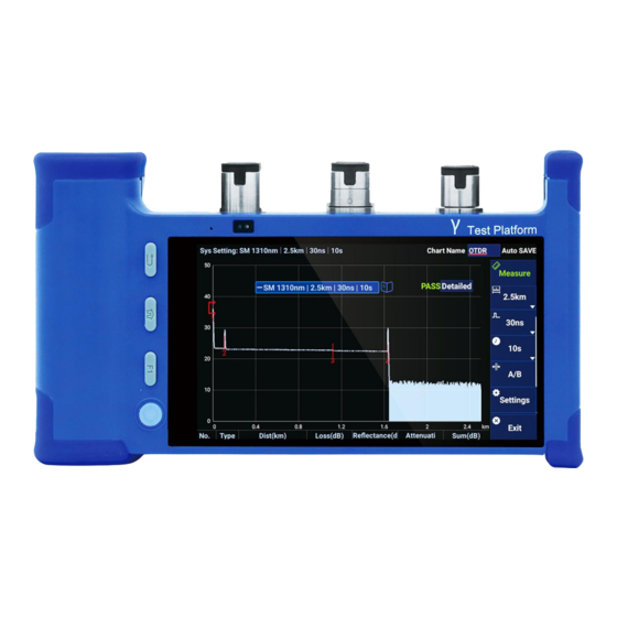
OTDR 4.Software introduction 4.1 OTDR introduce OTDR: On the far left is the OTDR software icon. Click to enter the optical fiber link diagram interface. It can intuitively display the event position, insertion loss and return loss information of the entire optical fiber link. - Page 22 OTDR Swipe up into the measurement main interface, which can be divided into four areas: area 1 is the parameter display area, area 2 is the curve display area, area 3 is the event point display area, area 4 is the function button area, and the functions of each area will be described below.
- Page 23 OTDR a) Start & Stop measuring button: without measurement, it is displayed as measurement, and click to start the measurement; During measurement, it is displayed as stop measurement, click to stop the measurement. During the main interface will indicate that the current software is in measurement. b) A / B calibration line button: you can help view the data of the curve (see 7.4-A / B function introduction for details).
-
Page 24: Introduction To Auxiliary Tools
OTDR 4.2 Introduction to auxiliary tools OPM-Laser-VFL icon: Click to enter the helper page. There are three detection tools in the helper interface, which are visible light source VFL, Invisible light source Laser, and optical power meter OPM (see 6.3 Auxiliary tool for details). System tool icon: click to enter the system tool page, the system tool page contains the camera, gallery, computer, clock and other common small tools. -
Page 25: Parameter Introduction
OTDR 5.Parameter introduction 5.1 Set the regular parameters Click the Settings button to open the Settings page to see the general parameter setting interface: Test mode: It currently supports manual mode, automatic mode, automatic distance mode, and real-time mode. In manual mode, you can customize wavelength type, test range, pulse, and duration. - Page 26 OTDR Wavelength: Click the "wavelength" column to switch the wavelength. The system provides two types of wavelengths (1310nm, 1501550nm) for measurement. You can also choose 1310 & 1550n. After selecting this wavelength, you will launch two wavelengths of 1310nm and 1550nm for measurement. ...
- Page 27 OTDR Pulse: Click the "pulse" column to switch the test range. This system provides 11 types of pulses (5ns, 10ns, 30ns, 50ns, 100ns, 275ns, 500ns, 1us, 2.5us, 10us, 20us). The selection of pulse needs to be changed according to the test range, and the selection of appropriate pulse can also improve the accuracy of the test.
- Page 28 OTDR Automatic zoom diameter distance: Click the "Auto zoom for fiber" column to enable automatic diameter distance or cancel the automatic diameter spacing, and automatically zoom the fiber diameter distance to set the curve display to show only the full curve view from the beginning of the curve to the end of the curve.
- Page 29 OTDR Display Event Area: Click the "Display trace grid" column to enable the display event area or undisplay or hide the event (fiber) area in the event pane, depending on the type of value to view. If the event area is displayed, the event pane contains the area length and area decay values.
-
Page 30: Set Threshold Parameters
OTDR 5.2 Set threshold parameters Click the Settings button to open the Settings page, and the sliding setting page can see the threshold parameter setting interface. The threshold parameter setting will affect the passage of the fiber or not: Wavelength: the "wavelength" column of threshold parameters can choose two types of wavelengths of 1310nm and 1550nm. - Page 31 OTDR For example, after the wavelength is 1310nm, the melting loss is adjusted to 0.06, and then the wavelength is 1550nm. It is found that the parameter in the column of 1 melting loss is still 0.5, which does not change. When the wavelength is only 1310nm again, the wavelength loss is displayed as 0.06.
-
Page 32: Set Link Parameters
OTDR Connector loss: The "Connector Loss" column in the threshold parameter can change the threshold value of connector loss. When "connector loss" is checked, the test results will verify the connector loss. When the connector loss in the measurement result is greater than the set value, the curve will not pass, and the range of connector loss is 0.06~5dB. -
Page 33: Set User Information
OTDR launch fiber lenght:To define the actual diameter origin of the fiber, you can set the launch fiber lenght. When testing the device, connect a startup fiber between the device and the fiber under test. This is why the fiber diameter distance contains the startup fiber by default. -
Page 34: Storage Settings
OTDR 5.5 Storage Settings Click the Settings button to open the Settings page, slide the Settings page can see the result save setting interface: File name: The file name is related to the name of the curve and the picture (the name composition of the curve is: file name + wavelength + ID) ID: used to distinguish the end of the saved file name, check the automatic growth, the ID will automatically add 1. - Page 35 OTDR Auto SAVE:The curve data is automatically saved after the measurement is completed, and the repeat will be asked whether to save it. SAVEPass:Only passing curves are saved after completion, and it is also asked after repetition. SAVEFail:Only curves that fail the measurement are saved, and it is also asked after repetition.
-
Page 36: Show Skin Settings
OTDR 5.6 Show skin settings Manual switching:The user can choose the skin type of the device by himself Automatic switching:The user does not need to switch the skin themselves, and the device will switch according to the current light intensity. Version:Displays the version number corresponding to the software installation. -
Page 37: Operation Guidelines
OTDR 6.Operation guidelines 6.1 Clean and connect the optical fibers ATTENTION: To ensure maximum power and avoid false readings: ● Always clean the end of the optical fiber according to the following instructions before inserting it into the port. OTDR is not responsible for damage or errors resulting from improper fiber cleaning or handling. -
Page 38: Otdr Test
OTDR 6.2 OTDR test The main menu is to click OTDR to enter the test selection item. During the OTDR test, specify the type of fiber mode and connect the fiber to the correct port to obtain the correct test curve and results.(1.2 Product composition, interface description) The measurement mode is divided into four types: manual measurement, automatic measurement, automatic distance measurement, and real-time mode. -
Page 39: The Operation Process For Automatic Measurement Mode
OTDR (recommended duration over 45s), click , select the measurement range, which recommend between 1.5 and 2 times the actual length of the optical fiber. Click to select the pulse size, and the pulse size can be selected by yourself.(Low pulse improves the event accuracy but has a small measurement range; high pulse improves the measurement range but the event accuracy decreases). - Page 40 OTDR Click on the OTDR icon to access the OTDR software. Select automatic mode from the mode dropdown menu (modes include manual and automatic, and the corresponding modules are different). Click on the wavelength dropdown menu to select the desired wavelength for testing (wavelength can be chosen freely, and 1310nm&1550nm are dual wavelengths, which will be measured continuously twice).
-
Page 41: 3To Sample The Curve In Automatic Distance Mode
OTDR 6.2.3To sample the curve in automatic distance mode: Properly clean the connector. Connect a launch fiber between the device under test and the OTDR port. If necessary, set the launch fiber length (refer to section 5.3 on setting link parameters). Click on the OTDR icon , launch the OTDR software, and then click on the Settings button to access the parameter setup interface. - Page 42 OTDR After the measurement is complete, the OTDR interface will display the measurement results. You can scroll up and down the screen to view detailed data for each event point. Use two fingers to zoom in and out on the curve interface. Use A/B to view specific information for each location.
-
Page 43: Auxiliary Tools Are Used
OTDR 6.3 Auxiliary tools are used By clicking the icon on the main interface, you can enter the auxiliary tool interface. There are two detection tools in the auxiliary tool interface: Visible Fault Locator (VFL) and Optical Power Meter (OPM). 6.3.1 Optical Power Measurement (OPM) Click the power meter option in the main menu interface to enter the optical power measurement interface... -
Page 44: Visual Identification Of Optical Fiber Failures (Vfl)
OTDR 6.3.2 Visual identification of optical fiber failures (VFL) Visual fault locator (VFL) can help you identify fiber bending, faulty connectors, fusion, and other causes of signal loss. At a faulty fiber location, the VFL emits a visible red signal from the private port that can be continuous (default) or flashing (1Hz). - Page 45 OTDR WARNING: When the VFL is active, the VFL port emits visible laser radiation. Please avoid exposure to radiation and do not look directly at the beam. Make sure that all unused ports are properly covered. VFL status can be selected in the subsequent interface by clicking VFL button in the main menu.
-
Page 46: Manage Test Results
OTDR 7.Manage test results 7.1 Detailed information interface After the curve measurement is complete, you can enter the detailed information page by clicking the “Detailed” button in the upper right corner of the interface. The detailed information interface is mainly composed of 4 areas: the summary information and the judgment results of the main display curve of the area 1. - Page 47 OTDR Area 1 mainly displays the summary information of the curve and the judgment results of the curve. The functions of specific parameters are as follows: Wavelength: the wavelength parameter for the current curve measurement. Status: The judgment result of the current curve (PASS represents the current curve test pass in green, FAIL represents the current curve test failure in red), and the parameters affecting the test results can be viewed (5.2 Set the threshold parameter).
- Page 48 OTDR Span length: the actual length of the measured optical fiber. Date Time: the time point when the fiber test is completed (read the system time acquisition). Cable、Fiber ID:when the fiber test is completed, the user sets the custom parameters, the symbols and numbers that can be used to set the tested fiber.
- Page 49 OTDR Avg. Splice Loss: the ratio of total welding loss to radial distance length, in dB / km. Max. Splice Loss: the maximum value of the loss column of welding events in the obtained event list. Span ORL: optical return loss of the whole optical fiber. Area 4 mainly displays the link parameters of the curve, and the functions of specific parameters are as follows: IOR: it can be changed manually in the setting page.
-
Page 50: Curve Interface
OTDR 7.2 Curve interface The curve pane displays the tested curve completely. And can be enlarged / shrink the curve: Double-click the curve interface to enlarge the x-axis of the curve... - Page 51 OTDR Double fingers horizontally separated and closed, the curve can be narrowed and enlarged operation, the minimum ratio of shrinkage is 1:1. After the curve is enlarged, you can swipe the screen to show the curves in other areas. At any time, when the curve of the curve interface is in the enlarged state, you can click the "1:1"...
- Page 52 OTDR Fiber-optic link diagram interface Curve interface...
-
Page 53: Event Point Interface
OTDR Event point interface 7.3 Event point interface The event number, event type, position / length, loss, reflectance, attenuation, accumulation are presented below:... - Page 54 OTDR The "event type" is generally divided into: starting point, melting point, reflection point, endpoint, and event area (see Appendix A for details) start point :With a special starting point mark, there is no loss value at this point, and the reflectivity is generally small fusion point :...
-
Page 55: A/B Function Introduction
OTDR Loss(dB): Display the loss of the event point or the loss of the event area. When this line of data is event point data, the value represents the loss at this event point. When this line of data is event area data, the value represents the loss between the upper and lower event points. - Page 56 OTDR A/B button:Click the button , and the A / B operation box can pop up. A: When clicking "A", a red line appears on the left side of the curve chart. Hold the red line with your fingers, you can drag the left and right drag line A to slide B: When you click "B", the yellow line appears on the right side of the curve chart.
-
Page 57: File Management
OTDR 7.5 File Management Click the "open" button on the main interface to view curves and pictures. The Test result interface can perform the following operations: LOOKOVER: Click “LOOKOVER” to redraw the saved curve information on the main interface, including the name of the curve, the parameters selected during the test and the event points. - Page 58 OTDR Select all: "Select all" can check all files at one time, and click again to cancel the selection. (the select all function will operate all curve data at the same time. Operate with caution) The picture display interface can perform the following operations: Double-click the picture to enlarge the graph, and then you can click the "Return"...
- Page 59 OTDR The report display interface can perform the following operations: LOOKOVER: Click “LOOKOVER” to redraw the saved curve information on the main interface, including the name of the curve, the parameters selected during the test and the event points. When there is a curve to be viewed on the screen, continue the viewing operation, which will cancel the currently viewed curve and replace it with the selected curve.
-
Page 60: Add Contrast Curve
OTDR 7.6 Add contrast curve When there is a test completed curve in the main interface, you can click the "comparison" button to add the comparison curve. At most five curves can be displayed on the graphical display interface: one main curve and four reference curves (if the corresponding function has been selected). - Page 61 OTDR When there are multiple comparison curves in the main interface, you can click the "Red Cross" button behind the information box to cancel the comparison of a single comparison curve, or click the "Cancel" button in the upper left corner to cancel all the comparison curves at the same time.
-
Page 62: Performance Indicators
OTDR 8.Performance indicators OTDR Model OT-100 OT-110 Wavelength (nm) 850/1310/1550/1625/1650 1310/1550/1625/1650 Dynamic Range (dB) Pulse Width (ns) 5/10/30/50/100/275/500/1000/2500/10000/20000 Event Dead Zone (m) Attenuation Dead Zone (m) Linearity (dB/dB) ±0.03 Loss Resolution (dB) 0.001 Distance Accuracy (m) ±(1 + 0.005% x distance + resolution Distance Range (km) 0.2~160... - Page 63 OTDR 630nm~670nm Operating Mode CW/1Hz Connector Type Universal FC/SC/ST/LC Operating Wavelength 1310nm/1550nm Operating Mode CW/270Hz/1kHz/2kHz Connector Type Universal FC/SC/ST/LC Other Power AC/DC adapter, input 100-240 VAC, 50-60 Hz, Power Supply output: 5V, 2A Lithium battery: 5V, 6400mAh Operating Temperature 0 °C t o 50 °C Storage Temperature –40 °C to 70 °C Humidity...
-
Page 64: Appendix A Event Type Description
OTDR Appendix A Event type description This section describes all types of events that may appear in the event table and generated by the application. The following is an explanatory Guide: ● each type of event has its own symbol ●... - Page 65 OTDR Continuous optical fiber This event indicates that the selected sampling range is shorter than the fiber length. ● the end of the fiber was not detected because the analysis process ended before the end of the fiber was reached. ●...
- Page 66 OTDR End of analysis This event indicates that the pulse width used does not provide a dynamic range sufficient to reach the end of the fiber. ● the analysis ends early before reaching the end of the optical fiber, which is caused by the low signal-to-noise ratio.
- Page 67 OTDR Non reflective event This event is characterized by the sudden reduction of Rayleigh backscattering signal level. It can be seen that there are discontinuities on the downward inclined curve signal slope. ● this event is usually caused by fusion point, macro bend or micro bend in optical fiber. ●...
- Page 68 OTDR Reflective event Reflection faults are displayed as spikes in the fiber curve. They are formed by a sudden break in the refractive index. ● reflection events cause a large part of the energy originally emitted to the optical fiber to be reflected back to the light source ●...
- Page 69 OTDR Gain event This event indicates a fusion point with obvious gain phenomenon, which is due to the different backscattering characteristics (backscattering and backscattering capture coefficient) of the two parts of optical fibers at the joint. ● the loss value of gain event has been specified, but the specified value does not represent the actual loss of this event.
- Page 70 OTDR Emission level This event indicates the level of signal transmitted to the fiber. ● the figure above shows how to measure the emission level. Using the least square approximation method, draw a straight line in the linear region between the first and second detection events to fit all curve points in the linear region.
- Page 71 OTDR Optical fiber area This symbol indicates that there are no events in the fiber area ● the sum of all optical fiber areas included in the whole optical fiber curve is equal to the total optical fiber factory. The events detected are always different - even if they all contain multiple points on the curve.
- Page 72 OTDR Merged reflection events This symbol indicates that the reflection event has been merged with one or more other reflection events. In the event table, the symbol also indicates the total loss caused by the combined reflection event. ● merged reflection events consist of reflection events. Only the merged reflection events are displayed in the event table, not the reflection sub events that make up it.
- Page 73 OTDR events, this line should be drawn in the linear area after the last merged event. Then, extend the line in the direction of the first merged event. ● the total loss (△ dB) is equal to the power difference between the starting point of the first event (point A) and the point on the extension line just below the first event (point B).
- Page 74 OTDR Reflection event (possible echo) This symbol indicates that the reflection event may be a real-time reflection or echo generated by another stronger reflection closer to the light source. ● in the above example, the transmitted pulse hits the third connector, is reflected back to OTDR and enters the optical fiber again.
-
Page 75: Appendix B Comparison Table Of English Abbreviations
OTDR Appendix B Comparison table of English abbreviations OTDR Optical Time Domain Reflectometer Optical Return Loss Index of Refraction Visual Fault Locator Single Mode Multi Mode Optical Power Meter Appendix C Company address Please contact Shenzhen Dimension Technology Co., Ltd. for machine troubleshooting, maintenance, equipment consultation and troubleshooting.
Need help?
Do you have a question about the OT-100 and is the answer not in the manual?
Questions and answers