Table of Contents
Advertisement
Advertisement
Table of Contents
Troubleshooting

Summary of Contents for SIUI SR-8230S
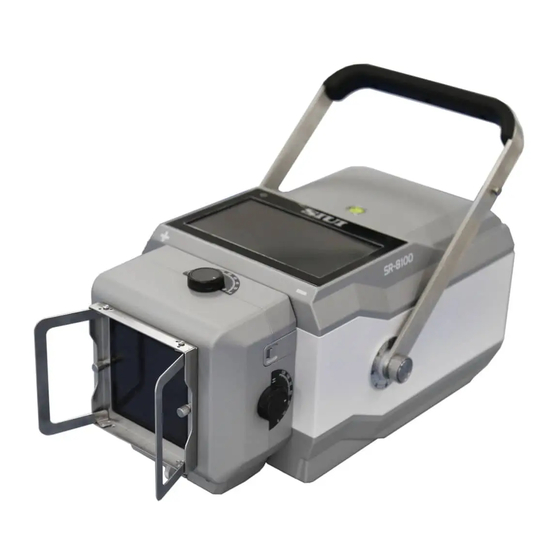
- Page 1 SSFRXA0V121END SR-8230S Portable X-Ray Unit OPERATION MANUAL...
- Page 3 For any questions, SIUI recommends that you consult your local management or regulatory authority for their advice. 3. SIUI is committed to providing users with better products and services based on the compliance with regulatory requirements. However, due to the continuous...
- Page 4 Statement device if: Damage or loss caused by improper operation or rough use. Damage or loss caused by Force majeure such as fire, earthquake, flood or lightning. Failure to comply with the conditions for use of this device, such as damage or loss caused by insufficient power supply, incorrect installation, environmental conditions that do not meet requirements, or related electrical equipment used does not meet national standards.
- Page 5 Service Instruction Service Instruction 1. SIUI will provide free service if failure happens under normal usage by obeying the operation manual during the warranty period. 2. No free service will be provided in the following condition. 1) Expiration of warranty period.
-
Page 7: Table Of Contents
Contents Contents Preface................................IV Chapter 1 General ........................... 1-1 Application Scope .......................... 1-1 Product ..............................1-1 Indications for Use .......................... 1-1 Specifications ........................... 1-2 Composition and Meaning of Model ..................1-2 Environmental Conditions......................1-2 Power Requirement for Normal Operation ................1-2 Impact to Environment and Energy .................. - Page 8 Contents Accessories ............................3-4 Option ..............................3-4 Chapter 4 Specifications ........................4-1 Specifications of Portable X-ray Unit ..................4-1 Specifications of X-ray Tube ....................... 4-2 Typical Exposure Technique Factors Setup for Reference ........... 4-5 Dimension and Weight ......................... 4-7 Chapter 5 Device Installation ....................... 5-1 Device Connection .........................
- Page 9 Contents Calibration Instruction ........................8-2 Quality Assurance ..........................8-4 Cleaning and disinfection ......................8-5 Environmental Protection Requirements ................8-6 Chapter 9 Storage, Transport and Package ..................9-1 Storage and Transport ........................9-1 Package Symbols ..........................9-1 Unpacking and Check ........................9-1 Appendix A Description of Symbols ....................
-
Page 11: Preface
Preface Preface To use this portable x-ray unit (“system”, “machine”, “device” or “unit”) correctly and safely and to ensure a long operation life, the user should thoroughly understand the device performance, functions, operations and maintenance. Please read this operation manual carefully before using the device. This device has been designed and manufactured with operator and patient safety considered. - Page 12 Preface 【DANGER】: Identifies a situation or operation that is known to be a particular hazard. Failure to follow this instruction could result in severe casualties or significant property damage. 【Warning】: Identifies a situation or operation that is known to be a particular hazard.
-
Page 13: Chapter 1 General
Multiple APR storage. 1.3 Indications for Use The SR-8230S Portable X-ray Unit is a portable X-ray device, intended for use by a qualified/trained physician or technician for the purpose of acquiring X-ray images of the desired parts of patient’s anatomy (including head, cervical spine, chest, abdomen, lumbar spine, pelvis and extremities). -
Page 14: Specifications
General Specifications a) The output power of portable X-ray unit is 5kW b) The output voltage of portable X-ray unit is 40 125kV c) The output current of portable X-ray unit is 10 100mA d) The small tube focus is 0.6mm.; The big tube focus is 1.8mm. Composition and Meaning of Model SR –... -
Page 15: Impact To Environment And Energy
General f) Class II equipment; The power supply of the portable X-ray unit is internal power supply. Impact to Environment and Energy a) Power-saving technology is used in the device. For example, instead of a conventional halogen lamp, a high-bright LED is used in the collimator, with the power only a few tenth of the halogen lamp. -
Page 16: Essential Performance
General c) Pregnant women undergoing X-ray exams may result in fetal injury. Clinicians’ decision shall be made by weighing the condition of patients. Despite X-ray harm to humans, the X-ray device will not result in any 【Warning】 danger provided that the operation is correct. Please ensure to meet safety requirements of the operation. - Page 17 The coefficient of variation of measured values of air kerma shall be not greater than 0.05 for any combination of loading factors. The device fundamental performance shall be tested once every 【Caution】 year by contacting SIUI service or a qualified agent.
-
Page 19: Chapter 2 Precautions For Safe Use
Precautions for Safe Use Chapter 2 Precautions for Safe Use Safe Use Period, Manufacture Date and Validity The device is valid for 10 years. The validity is a safe use period. For manufacture date, please see the label on the device enclosure. General Rules for Safe Use a) The device shall ONLY be used by medical practitioners with professional qualification or be used under the guidance of medical practitioners with... -
Page 20: Common Wrong Use Or Operation
Precautions for safe use Users should pay significant attention to X-Ray protection, so as to 【Warning】 prevent themselves or other persons from exposure as a result of negligence, errors or unawareness. All authorized personnel to operate the device shall fully understand the danger of exposure to X-ray. -
Page 21: Precautions In Special Cases (Power Failure, Transport)
Precautions for safe use side of the device to "OFF" position. Turn on the device only after receiving the confirmation from the manufacturer or the distributor that it is safe to do so. Precautions in Special Cases (Power Failure, Transport) In case any damage or failure is found in the device, do not use it before the problem is fixed by a qualified person. -
Page 22: Contraindications
Precautions for safe use Risk of exposure to hazardous radiation to the user or patient if safe 【Warning】 X-ray operation is not observed! Despite X-ray harm to humans, the X-ray device will not result in any 【DANGER】 danger provided that the operation is correct. Please ensure to meet safety requirements of the operation. -
Page 23: Emc Safety
Precautions for safe use 2.10 EMC Safety a) If any interference is produced from the device (confirmed by switching the device power switch state) , the user (or a qualified service person) should use one or more of the following means to fix the problem: ... - Page 24 Precautions for safe use This system has a network connection function, and data can be transmitted through the USB port of device interfaces from USB disk to the device, which facilitates SIUI engineer to perform program update to the device.
-
Page 25: Chapter 3 Composition And Operation Principle
Composition and Operation Principle Chapter 3 Composition and Operation Principle 3.1 Composition The product is mainly composed of SYS board, Touch screen, X-ray tube, high-voltage tank, collimator, lithium-ion battery, exposure hand switch and lithium-ion battery charger. Its structure is shown in Fig. 3-1. Collimator Touch screen SYS board... - Page 26 Composition and Operation Principle Fig. 3-2 System Operation Principle a) Power Supply and Power-On/Off Circuit The battery module is sent to the inversion module through the capacitance storage module, and the power supply is sent from the battery module to the power supply module (.
- Page 27 Composition and Operation Principle d) Principle of Tube Current Loop Control In the exposure process, signals sampled by the current sampling circuit are sent to the SYS board, by which a comparison is carried out between feedback signals and internal reference signals.
-
Page 28: Accessories
Composition and Operation Principle A self-test of the main unit control device is performed when powering up the device. During the operation, each unit is monitored, and protection action will be done if any abnormal situation occurs. Meanwhile the failure information is sent to the console and failure warning signals are given, with the error code displayed on the kV window. -
Page 29: Chapter 4 Specifications
Specifications Chapter 4 Specifications 4.1 Specifications of Portable X-ray Unit a) Charging input voltage: 50.4V b) Input power: battery 44.4V c) Max. output power: 5kW @ 125kV, 40mA d) Nominal power: 5kW @ 100kV, 50mA, 0.1s e) Adjustable range of tube voltage: 40 125kV, step value 1kV. -
Page 30: Specifications Of X-Ray Tube
Specifications p) SID: SID distance 1m in normal use, measured with the tape in the collimator. q) Maximum continuous heat loss: 250W r) Deviation between focus position and reference axis: ± 1° 4.2 Specifications of X-ray Tube 4.2.1 IEC classification: Class I, Type B 4.2.2 Main specifications Electrical parameters Circuit (neutral grounding) ……………………………………………………….………………………………...DC circuit... - Page 31 Specifications Fig. 4-1 Thermal Characteristics of Anode 4.2.4 As shown in Fig. 4-2.
- Page 32 Specifications Fig. 4-2...
-
Page 33: Typical Exposure Technique Factors Setup For Reference
Specifications 4.3 Typical Exposure Technique Factors Setup for Reference Adult application Distance: SID=1m Parts and aspect Size X-ray tube voltage Current time product Head (PA) Normal 72 kV 12.5 mAs Head (PA) 72 kV 16 mAs Head (PA) Slim 70 kV 12.5 mAs Head (LAT) Normal... - Page 34 Specifications Knee (AP) 70kV 6.3mAs Knee (AP) Slim 65kV 4mAs Knee (LAT) Normal 65kV 5mAs Knee (LAT) 70kV 6.3mAs Knee (LAT) Slim 65kV 4mAs Ankle (LAT) Normal 65kV 5mAs Ankle (LAT) 70kV 5mAs Ankle (LAT) Slim 65kV 4mAs Foot (AP) Normal 50kV 3.2mAs...
-
Page 35: Dimension And Weight
Specifications Note: Adult patients are divided into 3 categories of patient size (Normal, Fat and Slim) according to Body-Mass-Index (BMI). BMI is a person’s weight in kilograms divided by the square of height in meters. It is a standard commonly used internationally to measure the degree of body fatness and health. - Page 36 Specifications The glass tube and digital receptor module in the device are 【Warning】 valuable fragile components, which should be handled with care.
-
Page 37: Chapter 5 Device Installation
Device Installation 5.1 Device Connection Take the SR-8230S out of the case, and insert the red wire of the exposure hand switch as indicated in Fig. 5-1 to the “HAND SWITCH” exposure hand switch port on the rear cover of the portable X-ray machine. The red marks on both ends shall be connected easily. -
Page 38: Connection With Imaging Device
Device Installation 5.2 Connection with Imaging Device The image detector that can be used with the SR-8230s shall comply with the following basic requirements: Min. acceptable requirement of X-ray 40kV-125kV range Image Sensor a-Si (Amorphous Silicon) TFT Min. Effective Array 2304 x 2800 Min. -
Page 39: Instruction For Use Of Vertical Imaging Stand
Specifications consult our technical support personnel. Otherwise, the company will not be responsible for the maintenance and / or compensation caused by the failure of the device or the malfunction of the device caused by the user's modification of the device. Vertical imaging stand 5.3 Instruction for use of For safe and convenient use of the portable X-ray machine, this product can be... -
Page 40: Chapter 6 Use And Operation
Use and Operation Chapter 6 Use and Operation 6.1 Operation 6.1.1 Operation Buttons and Functions Fig. 6-1 Control Panel Control Part Type Functional Description To display information such as exposure status and device status. NORMAL means the device is in standby state and there is no abnormality. - Page 41 Use and Operation Control Part Type Functional Description If an abnormal state occurs, it will also be displayed in this area. The exposure level 1 is ready. When using the hand switch, long press EXP1ST the hand switch Level 1 till " "...
- Page 42 Use and Operation Control Part Type Functional Description indicator turns on and the X-ray machine EXP1ST makes a "Di" sound. Wait for " " being displayed, which means exposure EXP2ND level 1 is ready. Till " " is displayed and disappears, one exposure is completed.
- Page 43 Use and Operation Control Part Type Functional Description R′10 number system. The value of the parameter mA / ms can be determined by the parameter kV, and the exposure time can be determined by the parameter mAs / ms. The Regional selection area is divided into five parts: head, chest, upper limbs, abdomen, and lower limbs.
- Page 44 Use and Operation Control Part Type Functional Description Body types include Heavy, Normal, Slim and Child. You can click one of the body Select area types to quickly switch the exposure parameters. Collimator Light Button. For details, see Button section 6.4. APR parameter save button.
- Page 45 Use and Operation 6.1.2 Imaging Function Area a) Toggle the rocker switch on the back cover of the portable X-ray machine to "ON" and press button, Power up the device and turn on it to have a self-test. After the self-test the buzzer beeps 3 times, and the control panel is displayed.
- Page 46 Use and Operation g) When using the exposure hand switch, press the hand switch Level 2, or use the remote control to do nothing. When is displayed, the system enters the exposure state. When is displayed, the system completes a normal exposure. The user may release the exposure hand switch. h) Wait for 5s, then the user may repeat steps d) to g) and do another exposure.
- Page 47 Use and Operation Restore factory Menu Menu Menu Function defaults Reset the filament value, kV feedback control time and Reset wireless module. The system will shut down after reset. Set Two Steps Exposure or One Exposure Mode Two Steps Exposure Step Exposure Filament value adjustment Default filament...
- Page 48 Use and Operation Restore factory Menu Menu Menu Function defaults Screen Adjust the screen brightness. Brightness When On is selected, the screen Screen Flip flips 180 degrees. One-key Ready Time and One-key Delay Time One-key Ready Time setting: The default value is 5 seconds. The setting interval is [2, 15], and each adjustment is increased by 1 second.
-
Page 49: Power On/Off
Use and Operation Restore factory Menu Menu Menu Function defaults IP address of the X-ray unit, the Port, and the display of AP hotspot and password can be set; 5. Smart Config can be set in DR System Mode. Update Program upgrade via USB disk. - Page 50 Use and Operation getting prepared for exposure. When is displayed on the control panel, press Level 2 of the hand switch, and the device starts to output X-ray, displayed on the control panel till the end of exposure is displayed on the control panel.
- Page 51 Use and Operation Fig. 6-4 There is a One Step Exposure button on the back cover as shown in Fig. 6-5. Long press it for 2 seconds, is displayed on the control panel; press the exposure button again within the set time (2~15 seconds, and 5 seconds by default), and the exposure is triggered;...
-
Page 52: How To Use Collimator
Use and Operation Set up “Timing of Screen Blank” in Engineering Mode of 6.1.3 Engineering Mode Function and Operation. c) There is an icon in the upper right of the portable X-ray machine for power display. When the power is low, the device shall be recharged in time. -
Page 53: Program Update
Use and Operation machine horizontally, pull out the measuring ruler to 65cm, and vertically stand a white board at the end to face the collimator, light up the collimator light, and the collimator window is adjusted to its maximum. The light field border displayed on the whiteboard is not larger than 35cm ×... -
Page 54: Li-Ion Battery
Use and Operation If the display on the control panel is in disorder, the display 【Caution】 parameters go beyond normal range, or any other unpredictable abnormal situation occurs, DO NOT perform any operation. Cut off the power supply of the main unit immediately. Restart the device after 1 minute, and the device may return to normal usually. - Page 55 Use and Operation Fig. 6-9 6.6.2 Power requirements for charger Indicator: Yellow for disconnection or slow charge, or Orange for fast charge, and Green for full charge. Use the charger manufactured and configured by the company only. 【Caution】 The charging time shall not exceed 12 hours continuously, or it may cause damage to the lithium-ion battery.
- Page 56 Use and Operation Fig. 6-10 6.6.4 Precautions for using the lithium-ion battery Regarding the use of the lithium-ion battery in the device, please 【Caution】 note the following: Do not disassemble, open, shred or puncture the battery with metal. Do not expose the lithium-ion battery to heat or flame. Do not throw the lithium-ion battery into a fire.
-
Page 57: Use Of Exposure Remote Control
Use and Operation (or in a car heated by sunlight) ; do not immerse the battery in water or make it wet, otherwise it may cause the battery to heat up, malfunction, fire or explode. Use of exposure remote control The exposure remote control is used by the operator to achieve remote exposure control of the device. - Page 58 Use and Operation Press the "A" key Press the "B" key Fig. 6-12 Wait for 5s between two consecutive exposure operations and 【Caution】 expose according to 1:60 exposure time, otherwise normal exposure cannot be performed. If you operate the exposure, you will prompted "Preparing…"...
-
Page 59: Installation Of Handle Pads(Option)
Use and Operation range of mAs will be decreased. Installation of Handle Pads(Option) Prepare one portable X-ray unit and two handle pads. Firstalign one handle pad against the left handle of the portable X-ray unit. Be noted thatthe hookside of the handle padshall face outward. SeeFig. 6-13. Hookside outward Fig. - Page 60 Use and Operation Fig. 6-14 Fold the hook side of the handle pad inward. The notch shall bypass the screw on the handle.See Fig. 6-15. Hookside folded Fig. 6-15 After finishing the installation of the first handle pad, install the second handle pad. The second handle pad is symmetrical with the first one, and it will be installed on the right side of the carry handle of the portable X-ray unitfollowing steps b)~ d).
- Page 61 Use and Operation Fig. 6-16 ★Tip: The different colors of X-ray units do not affect the installation of the handle pads. Handle pads are options. If no optional hand pad is purchased, skip the step "6.8 Installation of Handle Pads". 6-22...
-
Page 62: Chapter 7 Safety Protection Device And Troubleshooting
Safety Protection Device and Troubleshooting Chapter 7 Safety Protection Device and Troubleshooting 7.1 Safety Protection Device and Precautions Fuse: to avoid overcurrent, short circuit, and battery burn. Temperature control switch: to protect the tube core. Over-current protection circuit To determine if over current occurs by monitoring battery capacity change when exposure. -
Page 63: Failure Analysis And Troubleshooting
Safety Protection Device and Troubleshooting 7.4 Failure Analysis and Troubleshooting Failure Diagnosis The device has a failure self-test function. If any key failure occurs, the device will give alarm, which facilitates failure inspection and troubleshooting. Generally, the first step to confirm a failure is to check if the voltage of the power supply is normal, and check all circuit boards for any failure. -
Page 64: Replaceable Components List
Safety Protection Device and Troubleshooting Click the error display area to clear LOW BATTERY Low battery the error and retest. If the error is still reported, recharge the battery. Click the error display area to clear the error and retest. If the error is still HIGH BATTERY High battery reported, shut down and contact the... -
Page 65: Chapter 8 Maintenance
Maintenance Chapter 8 Maintenance Regular maintenance can ensure that the device runs continuously and safely. Meanwhile with improved maintenance, damage (such as device downtime and repair) is reduced, and safety performance (personal injury) is improved. 8.1 General Maintenance The power must be switched off before starting maintenance. When the entire system is in working condition, do not try to clean any part of it. -
Page 66: Calibration Instruction
8.4 Calibration Instruction 【Caution】: This operation requires the X-ray unit to be tested in a protective room! The calibration procedure for the SR-8230S requires special tools and should be done by SIUI trained technicians only. Tools required:... - Page 67 Maaintenance hand switch. 【Caution】: Before exposure, the operator should make sure that the shielded room is closed. b) Use the hand switch for exposure. After the exposure is over, check the measured kV value of the X-ray quality tester. If the measured kV value is (100 ± 5) kV, the test is passed.
-
Page 68: Quality Assurance
8.5 Quality Assurance The following quality control inspections shall be trained and provided service by SIUI qualified engineers. The device has no cosmetic damage. The connection surface of the whole device enclosure is flat; the silk screen pattern is clear, positioned properly, and there is no oil stain. -
Page 69: Cleaning And Disinfection
If step e) fails to comply with the relevant essential performance requirements, please contact SIUI immediately, and SIUI’s qualified engineers are available for service. The items packed in the package carton shall match the items listed in the packing list in terms of models and quantity. -
Page 70: Environmental Protection Requirements
Maaintenance Do not remove the device enclosure, and do not disassemble or 【Caution】 modify any parts inside the device. Such actions may result in serious personal injury and device damage! When the device is powered up, DO NOT clean any part of the 【Caution】... -
Page 71: Chapter 9 Storage, Transport And Package
Storage, Transport and Package Chapter 9 Storage, Transport and Package 9.1 Storage and Transport a) Ambient temperature: -20 ℃~55 ℃ b) Relative humidity: ≤ 93% c) Atmospheric pressure: 500hPa ~ 1060hPa d) No corrosive gases, good ventilation Indoors e) Transport requirements are as required by the contract, and package symbols are compliant to requirements. - Page 72 Storage, Transport and Package c) The unit should be placed in the direction according to the carton symbol. Do not reverse the direction. d) Storage environment requirements: Temperature -20℃ ~ 55℃, relative humidity ≤93%, no source of corrosion, or strong power supply. e) Clean indoor environment with heat source.
-
Page 73: Appendix A Description Of Symbols
Description of Symbols Appendix A Description of Symbols Symbol IEC publication Description IEC 60878-5007 "ON" (power) IEC 60878-5008 "OFF" (power) IEC 60878-5009 Connected and stand-by IEC 60878-5031 Direct current IEC 60878-5032 Alternating current IEC 60878-5172 Charger: Class II equipment —— Indoor use only IEC 60878-5384 Light Indication of radiation field... - Page 74 Description of Symbols Symbol IEC publication Description IEC 60878-5840 Type B applied part IEC 60878-ISO Follow instructions for use 7010-M002 ISO 15223-1 Manufacturer Authorized representative in the ISO 15223-1 European Community ISO 15223-1 Serial number Symbol for the marking of electrical and electronics devices according to Directive 2012/19/EU.
-
Page 75: Appendix B Guidance And Manufacturer's Declaration
Group 1, Class A ISM equipment Medical Devices Directive as stated in EN 60601-1-2. 【Warning 1】: The use of accessories, sensors, and/ or cables not supplied by SIUI may lead to increase of electromagnetic radiation or decrease of electromagnetic immunity, consequently resulting in operation failure. - Page 76 Guidance and Manufacturer’s Declaration Guidance and manufacturer’s declaration – electromagnetic emission Emission test Compliance Mains terminal disturbance voltage Group 1 RF emissions CISPR 11 Radiated disturbance Class A RF emission CISPR 11 Harmonic emissions Complies IEC 61000-3-2 Voltage fluctuations/ flicker emissions Complies IEC 61000-3-3 Guidance and manufacturer’s declaration –...
- Page 77 Guidance and Manufacturer’s Declaration Guidance and manufacturer’s declaration – electromagnetic immunity Immunity test IEC 60601 test level Electrostatic ± 8 kV contact discharge (ESD) ± 2 kV, ± 4 kV, ± 8 kV, ± 15 kV air IEC 61000-4-2 Radiated RF 3 V/m electromagnetic 80 MHz –...
Need help?
Do you have a question about the SR-8230S and is the answer not in the manual?
Questions and answers