Table of Contents
Advertisement
Quick Links
Advertisement
Table of Contents

Related Manuals for LANGER EMV-Technik ICI-DP Set

Summary of Contents for LANGER EMV-Technik ICI-DP Set
- Page 1 LANGER DE-01728 Bannewitz ICI-DP set mail@langer-emv.de EMV-Technik www.langer-emv.com Operating Instructions ICI-DP Set Double Pulse Magnetic Field Source Set - Translation of the original German user manual into English - Copyright May 2023 Langer EMV-Technik GmbH - 1 / 37...
-
Page 2: Table Of Contents
Labelling and notes ........................ 6 Intended use .......................... 6 Foreseeable misuse ....................... 7 Requirements for personnel ....................7 Safety instructions ........................7 Scope of delivery ......................9 ICI-DP Set ........................10 System description ....................... 10 BPS 204 ..........................10 5.2.1 Overview ........................... 10 5.2.2 Delay line .......................... - Page 3 LANGER DE-01728 Bannewitz ICI-DP set mail@langer-emv.de EMV-Technik www.langer-emv.com Control via BPS 204-Client ..................24 Overview ..........................24 Detailed instructions for using the BPS 204-Client..............25 Setting the different operating modes ................... 26 Control via DLL ......................27 Measurement setup ....................28 Quick start .........................
-
Page 4: Declaration Of Conformity
Nöthnitzer Hang 31 01728 Bannewitz Germany Langer EMV-Technik GmbH hereby declares that the ICI-DP set, Double Pulse Magnetic Field Source set complies with the following relevant regulations: - EMC Directive 2014/30/EU - Low Voltage Directive 2014/35/EU - Restriction of the use of certain hazardous substances 2011/65/EU... -
Page 5: General Information
General information Storage of the operating instructions The operating instructions for the ICI-DP set ensure safe and efficient use. It must be kept near the device and must be accessible to the user at all times. Reading and understanding the operating instructions Read the user manual carefully and follow the instructions in this manual before using the appliance. -
Page 6: Security
The user must follow all information and instructions in this user manual. The ICI-DP set may only be used in an environment with a temperature of 10 to 30 degrees Celsius and a humidity of 20 to 85 per cent without condensation. -
Page 7: Foreseeable Misuse
Always check all attachments, measuring devices, cables and probes before using the ICI-DP set. Never use damaged or defective devices. Only employees of Langer EMV-Technik GmbH may open the ICI-DP probes or the BPS 204 and work on the electrical components and electrical cables. - Page 8 Electromagnetic near fields are generated on the probe due to its function. For this reason, persons with a cardiac device, such as a pacemaker, must not work on or approach the ICI-DP set during operation. - 8 / 37...
-
Page 9: Scope Of Delivery
LANGER DE-01728 Bannewitz ICI-DP set mail@langer-emv.de EMV-Technik www.langer-emv.com Scope of delivery DesignationType Quantity Double Pulse Magnetic Field Source (s) ICI-DP xxx Burst Power Station BPS 204 Communication cable, Fischer-Fischer SK FI-FI 7p 1m High-voltage cable, Fischer-Fischer HV FI-FI mini 1m... -
Page 10: Ici-Dp Set
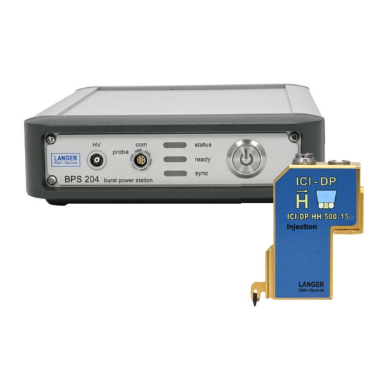
ICI-DP Set System description The ICI-DP set is used to couple fast transient pulses into ICs. The probes are optimised for high spatial and temporal resolution. This allows individual areas of ICs to be tested in a targeted manner. In addition to single pulses, it is also possible to generate double pulses. - Page 11 LANGER DE-01728 Bannewitz ICI-DP set mail@langer-emv.de EMV-Technik www.langer-emv.com The following figures show the connections of the BPS 204. Figure 3 shows the elements on the front, while Figure 4 shows those on the rear. The respective functions are described in Table 2:...
- Page 12 LANGER DE-01728 Bannewitz ICI-DP set mail@langer-emv.de EMV-Technik www.langer-emv.com Table 3: Elements of the BPS 204 Element Description of the Front view probe high-voltage socket Output of the internal high-voltage generator: The probe must be connected to the BPS using the high-voltage cable.
-
Page 13: Delay Line
LANGER DE-01728 Bannewitz ICI-DP set mail@langer-emv.de EMV-Technik www.langer-emv.com Figure 5 shows the block diagram of the BPS 204. The blocks shown in green can be controlled via the BPS 204-Client or the DLL. The adjustable parameters of the BPS 204 are:... -
Page 14: Ici-Dp Probes
LANGER DE-01728 Bannewitz ICI-DP set mail@langer-emv.de EMV-Technik www.langer-emv.com ICI-DP Probes 5.3.1 Overview The ICI-DP probes generate magnetic field pulses with different spatial resolutions. Tips with a diameter of 250 µm, 500 µm and 1000 µm are available. ICI-DP HH250-15 ICI-DP HH500-15... - Page 15 LANGER DE-01728 Bannewitz ICI-DP set mail@langer-emv.de EMV-Technik www.langer-emv.com Figure 7: Front and rear view of the ICI-DP (example ICI-DP HH500-15) Table 5: Elements of the ICI-DP Element Description High-voltage connection High-voltage input of the probe: Must be connected to the socket at probe BPS 204 via the high-voltage cable.
- Page 16 LANGER DE-01728 Bannewitz ICI-DP set mail@langer-emv.de EMV-Technik www.langer-emv.com Figure 8 shows the block diagram of the ICI-DP probe. Trigger 1 and 2, shown in green, can be controlled via the BPS 204-Client or the DLL or fed directly into the probe via an external signal.
-
Page 17: Measuring Outputs „Shunt Out 1 / 2
LANGER DE-01728 Bannewitz ICI-DP set mail@langer-emv.de EMV-Technik www.langer-emv.com 5.3.2 Measuring outputs „shunt out 1 / 2“ The two measurement outputs (shunt out 1 & shunt out 2) of the ICI-DP probe can be used to measure the internally generated pulse current. To do this, the outputs are connected to the inputs of an oscilloscope. -
Page 18: Operating Modes
Operating modes The ICI-DP set can generate single and double pulse sequences. In addition to the pulse intensity, the repetition frequency and the polarity, it is also possible to synchronise the generated pulses with external events and to set a delay between the external (trigger) event and the pulse(s). The desired pulse mode can be set using the BPS 204-Client software (see section 7) or via the supplied DLL (see section 8). -
Page 19: Synchronised Operation (Pulse Synchronised To External Event)
IC to be tested. At the ICI-DP set, this external trigger signal can be fed into the BPS 204 or the ICI-DP probe, depending on the desired functionality. Table 8 provides an overview of which trigger inputs should be used for which requirements. -
Page 20: Synchronised Double-Pulse Operation Via Bps 204 Sync Input Using Single Trigger
LANGER DE-01728 Bannewitz ICI-DP set mail@langer-emv.de EMV-Technik www.langer-emv.com Figure 13: Synchronised (single) pulse operation 6.2.2 Synchronised double-pulse operation via BPS 204 sync input using single trigger In this mode, a double pulse sequence can be generated using a single trigger signal. The setup still corresponds to that in Figure 12. -
Page 21: Synchronised Double Pulse Operation Via Bps 204 Sync Input Using Double Trigger
6.2.4 Synchronized (double) pulse operation via ICI-DP sync in 1 / 2 input In addition to the option of feeding the trigger signal into the BPS 204, the ICI-DP set also offers the option of triggering the pulses directly at the ICI-DP probe. This is particularly advantageous if... - Page 22 LANGER DE-01728 Bannewitz ICI-DP set mail@langer-emv.de EMV-Technik www.langer-emv.com Figure 16: Measurement setup for synchronized operation via the ICI-DP probe. Individual pulses can only be triggered by a trigger signal at sync in 1. A double pulse sequence can either be triggered by a trigger signal at sync in 1 and sync in 2 (cf. Figure 17) or by a double pulse trigger signal at sync in 1 (cf.
- Page 23 LANGER DE-01728 Bannewitz ICI-DP set mail@langer-emv.de EMV-Technik www.langer-emv.com Figure 18: Synchronized double pulse operation, double trigger, ICI-DP - 23 / 37...
-
Page 24: Control Via Bps 204-Client
LANGER DE-01728 Bannewitz ICI-DP set mail@langer-emv.de EMV-Technik www.langer-emv.com Control via BPS 204-Client The parameters of the BPS 204 and the ICI-DP probes connected to it can be set using the BPS 204-Client. Depending on the selected mode, some parameters are not available and are greyed out accordingly. -
Page 25: Detailed Instructions For Using The Bps 204-Client
LANGER DE-01728 Bannewitz ICI-DP set mail@langer-emv.de EMV-Technik www.langer-emv.com Detailed instructions for using the BPS 204-Client The BPS 204-Cclient offers various options for setting the high voltage (pulse level). 1. By clicking and moving the slider. To 2. click next to the slider button The current value is displayed in the text field. -
Page 26: Setting The Different Operating Modes
LANGER DE-01728 Bannewitz ICI-DP set mail@langer-emv.de EMV-Technik www.langer-emv.com Setting the different operating modes The following figures displays an example of the settings for some of the operating modes described in chapter 6. Figure 20: Free-running operation (pulses not Figure Synchronised... -
Page 27: Control Via Dll
LANGER DE-01728 Bannewitz ICI-DP set mail@langer-emv.de EMV-Technik www.langer-emv.com Figure Synchronised double-pulse operation with trigger via ICI-DP Control via DLL All parameters that can be set with the BPS 204-Client can also be defined using the DLL supplied. This can be used for your own measurement automation. Please refer to the information in the Programming Manual, which can be found on the USB stick supplied and in the installation folder of the BPS 204-Client. -
Page 28: Measurement Setup
Figure 23 shows a possible measurement setup of the ICI-DP set with an ICI-DP HH500-15 probe, which couples magnetic field pulses into a test IC (DUT). The components of the ICI-DP set used for this are listed in Table 9. - Page 29 LANGER DE-01728 Bannewitz ICI-DP set mail@langer-emv.de EMV-Technik www.langer-emv.com Table 9: components of the ICI-DP set Name Description ICI-DP HH500-15 Generates magnetic field pulses which couple into the test IC. BPS 204 High-voltage generator and control unit for the probe High voltage cable...
-
Page 30: Quick Start
LANGER DE-01728 Bannewitz ICI-DP set mail@langer-emv.de EMV-Technik www.langer-emv.com Quick start 1. Check all components used for damage. 2. Install the BPS 204-Client on your PC. 3. Connect the BPS 204 and an ICI-DP probe with the enclosed high-voltage and communication cable. -
Page 31: Technical Data
LANGER DE-01728 Bannewitz ICI-DP set mail@langer-emv.de EMV-Technik www.langer-emv.com Technical data ICI-DP HH 500-15 Probe Table 10: Technical parameters of the probe ICI-DP HH500-15 Power supply via BPS 204 Dimension of the probe tip Ø 500 µm External trigger inputs (sync 1 & sync 2) SSMB, max. - Page 32 LANGER DE-01728 Bannewitz ICI-DP set mail@langer-emv.de EMV-Technik www.langer-emv.com Figure 24: Typical time signals of the ICI-DP HH500-15 in double pulse mode. Orange: Voltage at measuring output 1 (shunt out 1) Blue: Voltage at measuring output 2 (shunt out 2) Green: induced voltage in measuring coil Purple: resulting flux density in the measuring coil.
-
Page 33: Bps 204 Burst Power Station
LANGER DE-01728 Bannewitz ICI-DP set mail@langer-emv.de EMV-Technik www.langer-emv.com BPS 204 Burst Power Station Table 11: Technical parameters of the BPS 204 Burst Power Station Output voltage ± (50 ... 1000) V BPS ready output BNC, max. 5 V External trigger input BNC, max. -
Page 34: Dimensions Of The Ici-Dp Probe
LANGER DE-01728 Bannewitz ICI-DP set mail@langer-emv.de EMV-Technik www.langer-emv.com Dimensions of the ICI-DP probe Figure 27: Dimensions of the ICI-DP probe in [mm] - 34 / 37... -
Page 35: Dimensions Of The Ici-Dp Probe With Varied Holder
LANGER DE-01728 Bannewitz ICI-DP set mail@langer-emv.de EMV-Technik www.langer-emv.com Dimensions of the ICI-DP probe with varied holder Figure 28: Dimensions of the ICI-DP probe in [mm] - 35 / 37... -
Page 36: Customer Service
Please contact us if you have any questions, comments or suggestions. You can reach us here: Monday - Friday 8:00 am to 3 pm Please contact us at: Address: Langer EMV-Technik GmbH Nöthnitzer Hang 31 01728 Bannewitz Germany Internet: https://www.langer-emv.com/ E-mail: mail@langer-emv.de... -
Page 37: Guarantee
This document may not be copied, reproduced or processed, duplicated or distributed using electronic systems, either in whole or in part, without the prior written authorisation of Langer EMV-Technik GmbH. The management of Langer EMV-Technik GmbH accepts no liability for damage resulting from the use of this printed information.
Need help?
Do you have a question about the ICI-DP Set and is the answer not in the manual?
Questions and answers