Table of Contents
Advertisement
Quick Links
Advertisement
Table of Contents

Related Manuals for Alfa Network A1960


Summary of Contents for Alfa Network A1960
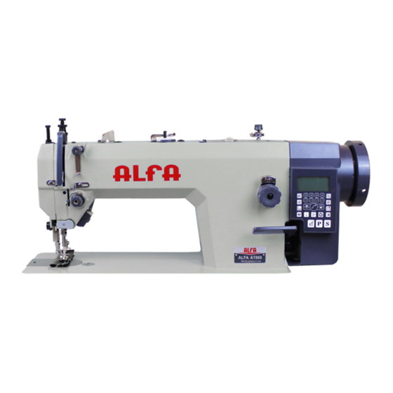
- Page 1 INSTRUCTION MANUAL INDUSTRIAL SEWING MACHINE A1960 Version nº: v1 Date: 15.03.24...
-
Page 5: Table Of Contents
INDEX 1. Brief introduction ............................1 2. Main specifications ............................1 3.Installing the oil pan (Fig.1)………………………………………………………………………………………………………………….1 4. Installing the mechanical head (Fig.2) ......................1 5. Installing the knee lifter assy. (Fig.3) ......................1 6. Adjusting knee lifter (Fig.4)..........................1 7. Lubrication (Fig.5) ............................1 8. -
Page 6: Brief Introduction
5. Installing the knee lifter assy. (Fig.3) 1. Brief introduction Insert the knee lifter assy. 1 into the shaft 2 under the This machine is designed with link type feed oil pan, and slightly tight the screw 3. mechanism and link lever thread take-up mechanism and full lubrication by pump. -
Page 7: Installing The Needle (Fig.7)
9. Installing the needle (Fig.7) 5.Hold the latch 4 and place the bobbin case in the hook. 1. Turn the machine pulley to move the needle bar 1 to its highest position. 13. Threading the needle thread (Fig.11) 2. Loosen the screw 2. 3. -
Page 8: Adjusting The Presser Foot Pressure (Fig.15)
1.Lower the presser foot. 6. Puli the needle thread down until the spring 1 is at 2.Adjust by turning the thread tension nut 2. the same height with the upper surface of thread guide 3 and then measure the tension of the spring. 7. -
Page 9: Adjusting The Difference Of Stitch Length Between The Forward And Back Tracking (Fig.22)
2. Loosen the screw 7. reference mark, make the third screw 5 of eccentric 3. Turn the feed bracket shaft in the direction of the wheel UD slightly lower than the reference mark arrow within a range of 90 with respect to the standard screw 4. -
Page 10: Adjusting The Oil Pump (Fig.27)
2. Loosen the screw 7 and make the hook tip aimed at Loosen the nut 7 and move the slide block 8 Upward: the center of needle 6, the clearance between the decrease the distance L to make the feed amount be hook tip and needle should be 0.05mm. -
Page 11: Clean (Fig.35)
The clearance between movable knife 1 and needle 3. Clean the feed dog with a soft brush. center is 7.5mm, and the clearance between fixed 4. lnstall the needle plate 2 by two screws 1. knife 2 and needle center is 5mm. 5.Turn the machine pulley slowly and check if the (2) Set the solenoid active, the movable knife 1 will needle drops into the hole center of needle plate...
Need help?
Do you have a question about the A1960 and is the answer not in the manual?
Questions and answers