
Related Manuals for go-e CH-30-01

Summary of Contents for go-e CH-30-01
- Page 1 Installation and operating manual go-e Controller valid for article number: CH-30-01 V 1.1...
- Page 2 Installation and operating manual go-e Controller | V 1.1...
-
Page 3: Table Of Contents
Commissioning/operation on the device Page 18 Commissioning/operation via app Page 33 PV Surplus Charging/Load Balancing Page 42 Warranty and exclusion Page 47 CE Declaration of Conformity Page 47 Contact and support Page 49 Installation and operating manual go-e Controller | V 1.1... -
Page 4: Important Symbols
The go-e Controller is compatible with all PV in- The go-e Controller helps you as a so-called verters* and AC electricity battery storage solu- energy management system (EMS) in an electri- tions. -
Page 5: Note Before Installation And Commissioning
The go-e Controller can be controlled directly via a display. The go-e app makes it even more convenient to use. Read the instructions and the data sheet care- fully and keep them for future reference. -
Page 6: Safety Regulations/Notes
PV system or to implement dynamic load nal regulations. management in interaction with go-e Chargers. The go-e Controller must be mounted by a qua- Failure to comply with the safety regulations lified electrician in accordance with the comple- can have serious consequences. - Page 7 Alternative current transformers, which are also suitable for higher currents, may be used The copyright to these operating instructions is only after inquiry to go-e support and its confir- held by go-e GmbH. mation in text form. All texts and illustrations correspond to the...
-
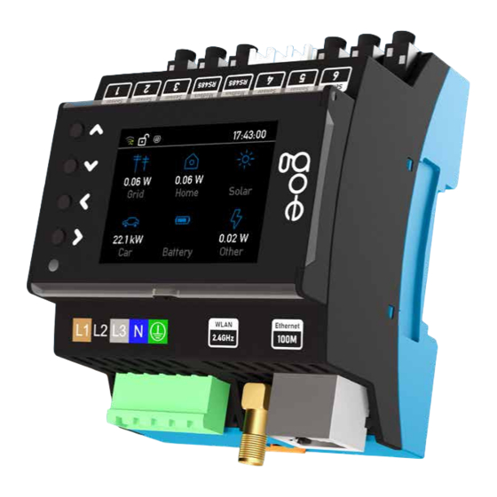
Page 8: Product Overview
WiFi-antenna 2.4 GHz Sensors 4-6 4 keys for menu navigation Ethernet 100 Mbit/s Brightness sensor Type plate Display switches off automatically with serial number of the Controller Back L1 L2 L3 N Installation and operating manual go-e Controller | V 1.1... -
Page 9: Scope Of Delivery
6. Scope of delivery go-e Controller WiFi antenna, self-adhesive optionally connectable Ethernet flat cable 2 m optionally connectable Connecting clamp 6 Current transformers foldable, 100 A with jack plug (90 degrees) Data card Installation and operating manual go-e Controller | V 1.1... -
Page 10: Technical Data
L1 - L2 L1 - L3 400 V L2 - L3 Inputs for current measurement Sinus Peak max. measurable current 100 A 144 A max. permanent current 140 A (thermally limited) Installation and operating manual go-e Controller | V 1.1... - Page 11 Charger in local network with mDNS number and password input not via the go-e app / go-e cloud / Log data recording and export display. Own data acquisition via with measured values API possible...
- Page 12 The firmware of both pro- ducts can be updated, for example, via the go-e app in the menu item "Internet". Installation and operating manual go-e Controller | V 1.1...
- Page 13 RCD/FI L1 L2 L3 N 0 6 5 1 0 Installation and operating manual go-e Controller | V 1.1...
-
Page 14: Installation
Required tools Screwdriver Ensure that the circuit is de-energised by ob- serving the five electrical safety rules. Mount the go-e Controller on the DIN rail. We Optional recommend mounting according to the illus- tration. However, the Controller can also be mounted rotated by 180°. - Page 15 *If it is not possible to install the current sen- sors with the arrow pointing in the specified direction for space reasons, the sensors can also be inverted via the Controller menu or the app. Installation and operating manual go-e Controller | V 1.1...
-
Page 16: Installation (Additional Sensors)
For an AC battery, the ar- verter to the distribution board. row on the current transformer should point from the battery to the distributor. Installation and operating manual go-e Controller | V 1.1... - Page 17 IP address. This works best with repeaters from the same brand of your access point or WiFi router. Installation and operating manual go-e Controller | V 1.1...
-
Page 18: Commissioning/Operation On The Device
L1 L2 L3 N 1. Start screen As soon as the go-e Controller is ready for operation, you can already see the first measured values on the home screen, which are probably still incorrect. The sen- sor configuration is described later. - Page 19 3. Settings / Device Press the > button to select the menu item "De- vice". Here you can, for example, adjust the lan- guage or the display of the go-e Controller to your wishes. 4. Device In the submenu "Device" you can e.g.: rotate the display by 180°...
- Page 20 In order for the power calculation to be correct, the phase must be set correctly. Imagine that the sensor measures 2 amps on your mains Installation and operating manual go-e Controller | V 1.1...
- Page 21 If the power factors are Controller try to regulate it as much as possible incorrect and, for example, only plus or minus to zero during PV surplus charging. Installation and operating manual go-e Controller | V 1.1...
- Page 22 However, if you have a three-phase inverter and Power grid Sensor 4 Solar: Factor 3 Home: Factor 3 Home Sensors 1-3 Grid: Factor 1 Home: Factor 1 Installation and operating manual go-e Controller | V 1.1...
- Page 23 Controller, you cannot measure it directly. As already mentioned, this does not matter for PV surplus charging. other loads Power grid other loads Home distance too far Installation and operating manual go-e Controller | V 1.1...
- Page 24 > key. 12. Sensors / Voltage phase assignments Optional step: Select the phase for which you want to change the assignment with the > key. Installation and operating manual go-e Controller | V 1.1...
- Page 25 PV surplus charging or dynamic load balancing. In addition, you can then connect to the Cont- roller locally without the cloud via the go-e app. Tip: The WiFi and Ethernet settings can perhaps be made even more conveniently via the go-e app.
- Page 26 Press the > key to select the menu item "Time". Advanced users can synchronise the time via an NTP server or the app. If the go-e Controller is connected to the go-e Cloud via the Internet, it always receives the current time from this. In this case, no settings are required here.
- Page 27 19. Main menu / Chargers Now it's time to connect your go-e Controller to one or more go-e Chargers. Press the > key to select the "Chargers" menu item. Than you can theoretically connect an in- finite number of go-e Chargers.
- Page 28 22. Settings / Outputs Press the > key to select the "Powers" menu item. 23. Outputs In this submenu you can see the current power of the individual categories. Installation and operating manual go-e Controller | V 1.1...
- Page 29 Press the > key to select the "Energies" menu item. 25. Energies In this submenu you can see for each category its current energy. 26. Settings / Categories Press the > key to select the menu item "Cate- gories". Installation and operating manual go-e Controller | V 1.1...
- Page 30 Press the > key to select the "Factory Reset" menu item. Reset the Controller to factory settings in this submenu if necessary. Either completely or only for a part of the configuration. Installation and operating manual go-e Controller | V 1.1...
- Page 31 Controller. 32. Settings / Webserver For experts and integrators: Press the > key to select the "Webserver" menu item. In this submenu you can enable or disable the local HTTP API. Installation and operating manual go-e Controller | V 1.1...
- Page 32 35. Settings / MEC Meter For experts and integrators: Press the > key to select the "MEC Meter" menu item. This submenu allows you to connect to a MEC meter and set categories for it. Installation and operating manual go-e Controller | V 1.1...
- Page 33 Controller into the app is mandatory. If you have already set up a go-e Charger, you have to go back to the device list. If the go-e Controller was already set up, you would see it in the device list. If you haven't set up the Con- troller yet, press "Add or setup device"...
- Page 34 Controller data card. The process is si- milar to the setup for the go-e Charger. Setup in app If you want to add an already set up go-e Con- troller, select "go-e Add device" and enter the serial number of the Controller. You can also find this on the data card enclosed with the Controller.
- Page 35 In the "Information" tab you can see diagrams of your energy flows during the last hours. It is also possible to export all data from the go-e Controller and view it on the PC. Settings In the "Settings" menu item of the app, you can...
- Page 36 "Settings", submenu "Sensors Configuration / Sensors" and read their voltages, currents and powers in real time after selecting them. You can also do this directly on the go-e Controller. Voltage sensors L1 to L3 always measure the voltage of the connected phases and current sensors Internal 1 to Internal 6 measure the current and power.
- Page 37 If you want to adjust an assigned load catego- ry or change the phase assignment, this is also possible here in the overview of the respective current sensor. This works similar to the menu of the go-e Controller itself. Installation and operating manual go-e Controller | V 1.1...
- Page 38 1 to this load in the category "Grid". If you do not have a separate sensor on the load branch, in other words the rest of your house- Installation and operating manual go-e Controller | V 1.1...
- Page 39 Settings / General / Date Time Settings Advanced users can synchronize the time via an NTP server or the app. If the go-e Controller is connected to the go-e Cloud via the Internet, it always receives the current time through this.
- Page 40 In the subitem "About you can view informa- tion about the hardware. There you will find, for example, the serial number. You can also download the latest firmware. Installation and operating manual go-e Controller | V 1.1...
- Page 41 Tap on "Device list" at the top right. There, se- lect the Charger for which you want to make settings for PV surplus charging or load balan- cing. Installation and operating manual go-e Controller | V 1.1...
- Page 42 11 PV Surplus Charging / Load Balancing Home screen (go-e Charger) After switching from your go-e Controller to the go-e Charger, you will be taken to its home screen with the "Charger" view. Remember these mode buttons (Eco, Daily Trip), which you will need to tap later if you want to activate PV surplus charging.
- Page 43 To do this, select the "Eco" tab in the menu bar below and then "PV surplus". If you have an electricity provider with flexible electricity prices that is listed in the go-e app, you can combine PV surplus charging with the corresponding electricity tariff.
- Page 44 You can also combine PV Surplus charging with the Daily Trip mode. If you want to be sure that the go-e Charger will charge your EV with a certain amount of energy until the morning and you want to use PV electricity or cheap grid electricity from an electricity provider with fle- xible tariffs, then you should activate the "Daily...
- Page 45 Charger simply charges when there is sur- plus PV power available - possibly not at all. In Next Trip mode, the go-e Charger tries to wait as long as possible for surplus power, but then charges power from the grid as late as possible to reach your desired amount of energy.
- Page 46 "Maximum grid current" line. This is the maximum current in amperes that your house can draw from the grid. The go-e Controller will ensure that this value is never exceeded when charging your electric car in combination with the power demand of your other consumers.
- Page 47 3. In the event of a guarantee claim, the customer has to inform go-e GmbH immediately in text form to com- plain about the defect. In the event of a justified notice of defect, go-e is obli¬ged to improve or replace the goods as soon as possible or to arrange this.
- Page 48 Installation and operating manual go-e Controller | V 1.1...
- Page 49 Support go-e GmbH Satellitenstraße 1 9560 Feldkirchen AUSTRIA support@go-e.com +43 4276 62400 www.go-e.com Online support Online support www.go-e.com Installation and operating manual go-e Controller | V 1.1...
- Page 50 Installation and operating manual go-e Controller | V 1.1...
Need help?
Do you have a question about the CH-30-01 and is the answer not in the manual?
Questions and answers