Table of Contents
Advertisement
Quick Links
Advertisement
Table of Contents

Related Manuals for Remberg COMPARA-2R+

Summary of Contents for Remberg COMPARA-2R+
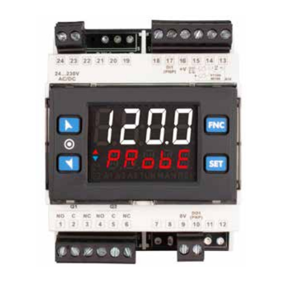
- Page 1 COMPARA-2R+ Controlador / Regulador Manual de usuario...
-
Page 2: Table Of Contents
Table of contents Safety guidelines ....................................3 Organization of safety notices ............................3 Safety Precautions ................................4 Precautions for safe use ..............................4 Model Identification ....................................4 Technical Data ......................................4 General Features ................................4 Hardware Features ................................4 Software Features ................................5 Programming mode ................................5 Dimensions and Installation ................................5 Electrical wirings ....................................5 Wiring diagram ..................................6 5.1.a Power Supply ................................6... -
Page 3: Safety Guidelines
Introduction The controller stands out for the bright display which ensures optimal visibility and increased level of information for the operator beside a scrolling Help function. These controllers relies on flagship programming mode by NFC/RFID technology with dedicated App PROGRAMADOR-NFC-Plus for Android devices (same already used for signal converters and indicators) not requiring wirings and power supply, allowing quick set-up/updates on site. -
Page 4: Precautions For Safe Use
• Installing two or more controllers in close proximity might lead to increased internal temperature and this might shorten the life cycle of electronic components. It is strongly recommended to install cooling fans or other air-conditioning devices inside the control cabinet. •... -
Page 5: Software Features
Software Features Regulation algorithms ON-OFF with hysteresis. - P, PI, PID, PD with proportional time Proportional band 0..9999°C o °F Integral time 0,0..999,9 sec (0 excludes) Derivative time 0,0..999,9 sec (0 excludes) Manual or automatic Tuning, selectable alarm, protection of command and alarm Controller functions setpoints. -
Page 6: Wiring Diagram
Wiring diagram 24 23 22 21 20 19 18 17 16 15 14 13 24...230V (PNP) PT100 AC/DC NI100 A\V NO C NC NO C NC 0V (PNP) 9 10 11 12 Power Supply 5.1.a SUPPLY Switching power supply 24..230 VAC/VDC ±15% 50/60 Hz - (ATR224) and 9 Watt/VA . 24...230 Galvanic insulation. -
Page 7: Relay Output Q1 - Q2
Relay output Q1 - Q2 5.1.e Capacity 5 A / 250 VAC for resistive loads. 230V 230V See chart below. Life Curve AC250V DC30 V AC125 V AC125V COS ø=0.4 Electrical endurance Q1 - Q2: DC30 V t=7ms 5 A, 250 VAC, resistive loads, 10 operations. -
Page 8: Controller Functions
Controller Functions Modification of main and alarm setpoint value Setpoint value can be modified from keyboard as follows: Press Display Value on display 2 changes. Increases or decreases the main setpoint value. Visualizes the other setpoints on display 1. Display 2 shows the setpoint type. -
Page 9: Automatic / Manual Regulation For % Output Control
Automatic / Manual regulation for % output control This function allows to switch from automatic functioning to manual command of the output percentage. With par. 48 (for regulation loop 1) it is possible to select two modes. A.ma. 1 . 1 First selection ) allows to enable with the writing... -
Page 10: Reading And Configuration Through Nfc
Reading and configuration through NFC Programmable via RFID /NFC. No wiring required! The controller is supported by the App PROGRAMADOR-NFC-Plus: using an ANDROID smartphone with NFC connection it is possible to program the device without using a dedicated equipment. The App allows to read, set and backup all parameters which are stored into the internal memory of devices. -
Page 11: Configuration Loading From Memory Card
Configuration loading from memory card In order to charge a configuration previously created and saved in the memory card, connect it to the micro-USB connector and power the instrument. Now, if the memory is detected and its data are considered valid, it is possible to view on the display memo ... -
Page 12: Table Of Configuration Parameters
Table of configuration parameters GROUP A - - Analogue input A. i n. 1 1 Sensor Ai SEN. 1 Analogue input configuration / sensor Ai selection Tc-K -260° C..1360° C. (Default) tc. k Tc-S -40° C..1760° C tc. s Tc-R -40°... - Page 13 8 Offset Calibration Ai o.cA. 1 Ai Offset calibration. Value added/subtracted to the process value (ex: usually correcting the ambient temperature value). ] (degrees.tenths for temperature sensors). Default 0. -9999..+9999 digit 1 p. 22 9 Gain Calibration Ai G.ca. 1 Value multiplied to the process value to calibrate the working point.
- Page 14 39 c.HY. 1 Command Hysteresis Hysteresis to control process in ON/OFF. -9999..+9999 [digit ] (degrees.tenths for temperature sensors). Default 0.2. 1 p. 22 40 L.L.S. 1 Lower Limit Setpoint Lower limit setpoint selectable for command setpoint . -9999..+9999 [digit ] (degrees.tenths for temperature sensors).
- Page 15 51 i.SP. 1 Initial Value Setpoint Determines the initial value (at start) of setpoint of command when is selected on parameter 46 FR.iN. (Command Setpoint Protection ) c.S.p .1 -9999..+9999 [digit ] (degrees for temperature sensors). Default 0. 1 p. 22 GROUP E - - Autotuning and PID reG.
- Page 16 88 U.L.p. 1 Upper Limit Output Percentage Selects max. value for command output percentage. 0%...100%, Default: 100%. 89 m.G.t. 1 Max Gap Tune Selects the max. process-setpoint gap beyond which the automatic tune recalculates PID parameters of process. 0-10000 [digit ] (degrees.tenths for temp.
- Page 17 129 A. 1 .L.L. Alarm 1 Lower Limit Lower limit selectable for the alarm 1 setpoint. -9999..+9999 [digit ] (degrees for temp. sensors). Default 0. 1 p. 22 130 A. 1 .u.L. Alarm 1 Upper Limit Upper limit selectable for the alarm 1 setpoint -9999..+9999 [digit ] (degrees for temp.
- Page 18 144 A.2.5.o. Alarm 2 State Output Alarm2 output contact and intervention type. (N.O. Start) Normally open, active at start (Default) n.o. St. (N.C. Start) Normally closed, active at start n.c. St. (N.O. Threshold) Normally open, active on reaching alarm 2 p. 22 n.o.
- Page 19 154 A.2.Lb. Alarm 2 Label Selects the message displayed in case of alarm 2 intervention. Disabled. (Default disab. 14.1 Message 1 (see table on paragraph lb. 01 14.1 Message 20 (see table on paragraph lb. 20 Custom message (modifiable by the user through the App or via modbus) user.l.
-
Page 20: Alarm Intervention Modes
278 vi.d.2 Visualization Display 2 Selects visualization on display 2. Command 1 setpoint (Default) c.1.SPv Percentage of command output 1 ou.Pe.1 279 tMo.d. Timeout Display Determines the display timeout Disabled. Display always ON (Default) 10 minutes diSab. 10Min 15 seconds 30 minutes 1S S 30Min... -
Page 21: Absolute Or Threshold Alarm Referred To Command Setpoint Active Over
Absolute or threshold alarm referred to command setpoint active over 12.c (par. 123 AL. 1 .F. Ab.c.u.A. Alarm Spv Absolute alarm referred to command setpoint Hysteresis parameter > 0 active over. Hysteresis value greater than “0” Command Spv (Par. 128 >... -
Page 22: Lower Deviation Alarm (Par. 123 = )
Lower deviation alarm (par. 123 12.h AL. 1 .F. Lo.dev. Lower deviation Lower deviation alarm alarm value of alarm value of alarm setpoint greater than setpoint less than Hysteresis parameter > 0 “0” and hysteresis “0” and hysteresis Command Spv Hysteresis parameter Alarm Spv ... - Page 23 Table of configuration parameters GROUP A - A. i n. 1 - Analogue input GROUP G - AL. 1 - Alarm 1 SEN. 1 Sensor Ai AL. 1 .f. Alarm 1 Function d.P. 1 Decimal Point A.I .5.o. Alarm 1 State Output Degree Alarm 1 Hysteresis ...
- Page 24 Antes de usar el dispositivo leer con atención las informaciones de seguridad y configuración contenidas en este manual. www.remberg.es...
Need help?
Do you have a question about the COMPARA-2R+ and is the answer not in the manual?
Questions and answers