Table of Contents
Advertisement
Quick Links
CONTROL BOX
FOR AUTOMATIC
POOL COVER
MOTORS
Installation and user's guide
Reproducing this document for other reasons than personal usage and more specifically its
publishing by any possible media including Internet, is strictly forbidden without an explicit and
written authorisation from UNICUM ; this authorisation can be eventually required by email at the
following address:
Ref : UNIBOX GB 120-06
transmission@unicum.fr
ZAC de Montrambert - Pigeot, 42150 La Ricamarie - France
Tel : +33 4 77 33 36 96 - Fax : +33 4 77 34 12 01
Email : transmission@unicum.fr -
Installation and user guide
www.unicum.tech
Page : 1
Advertisement
Table of Contents

Summary of Contents for Unicum UNIBOX 120
- Page 1 Reproducing this document for other reasons than personal usage and more specifically its publishing by any possible media including Internet, is strictly forbidden without an explicit and written authorisation from UNICUM ; this authorisation can be eventually required by email at the following address: transmission@unicum.fr...
-
Page 2: Important Safety Instructions
Keep the keys switch or remotes out of children’s reach. Only a responsible adult should operate the mechanism. READ AND FOLLOW ALL INSTRUCTIONS - STORE THESE INSTRUCTIONS LEAFLET VERSION DATE VERSION MODIFICATIONS 12/2020 UNIBOX 120 V1 03/2021 Modification in troubleshooting and pictures. 05/2021 Fuse characteristics + troubleshooting 02/2022 Inductive sensor + troubleshooting + others 08/2022 Added chapter 2.3... -
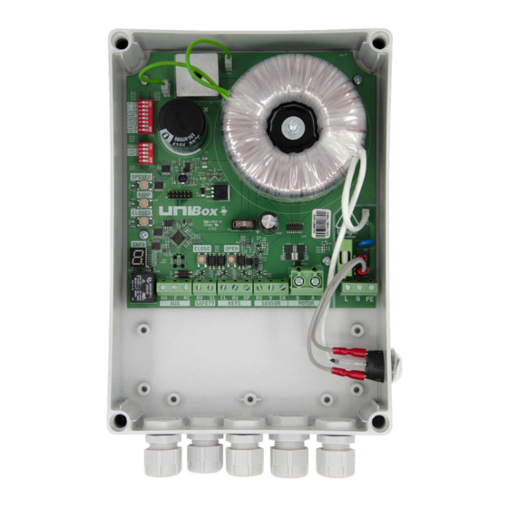
Page 3: Technical Data
Installation and user guide Technical data Board architecture and main components Switches for configuring advanced functions. 2) Switches for FORCED mode and other board configuration. 3) Button to program the "open" limit switch position. 4) Button to program the end of the speed ramp when closing the pool. 5) Button to program the "closed"... - Page 4 15) Fuse of the alternating circuit (1.6A 250VAC time lac, ceramic, cylindrical 5x20mm). 16) Engine protection fuse (5A, 32V ATO mini 10.9 mm). 17) Jumper for UNICUM motor with inductive sensor Note: Box compatible with PL1210, PL2010, DL1310 motors. 2.2 Available advanced functions •...
-
Page 5: Technical Specifications
Permissible altitude up to 2000 Pollution degree Note: UNIBox 120: control box compatible with PL1210, PL2010, DL1310, UNIMOT Elec This control box is compliant with EN 61800-5-1 standard. This control box has been tested under EMC standard EN 61800-3. Device does not include motor overheat protection. -
Page 6: Installation
Installation and user guide Installation WARNING FOR YOUR SAFETY - The installation of this product must be carried out by an authorised and qualified technician according to NF-C 18-510 or EN 50110-1. Definition of qualified personnel according to the NF C 18-510 standard: "person with appropriate training, knowledge and experience in electricity to enable him/her to analyse the electrical risk and avoid the dangers that electricity can present". -
Page 7: Electrical Connections
Motor Safety loop NOTE: This wiring schema is valid for a UNICUM motor equipped with mechanical sensor (MLS). WARNING FOR YOUR SAFETY - Connections are to be made by a QUALIFIED and HABILITATED person. Electrical connections must comply with the C15-100 standard in France the HD 384-7-702 standard in Europe. - Page 8 3.6.2 PNP inductive sensor (standard for older UNICUM motors): The UNIBOX 120 box can be used to replace old AN1072 boxes; in this case it is necessary to check whether the motor installed in the winding tube was equipped with a three-wire inductive sensor. In this case, in addition to connecting cables as shown below, it is necessary to close the bridge by connecting the two pins on the P205 connector on the board, using the jumper (see photo and chapter 2.1 point 17).
-
Page 9: Auxiliary Relay
(To activate an electrolysis system or other) D Dry contact 3A 30VDC, with common (COM) and contacts rest (NC) / work (NO). Auxiliary relay status: Auxiliary 1: Closed position info: Aux 1 : Unibox 120 Opened end position Motor closing Motor not moving... -
Page 10: Safety Loop
Installation and user guide Safety Loop : This terminal allows the serial connection of one or more devices that prevent the operation of the cover, under certain circumstances such as a water level sensor being activated, an emergency stop, etc... The cut-off device shall be fitted with a closed contact at rest which, once activated, shall open the safety loop stopping the engine, and preventing it from working. - Page 11 Installation and user guide Operation of the control box General Power is switched on using the illuminated switch on the side of the cabinet. The light switch As soon as the power is switched on, the switch lights up. You can check the initialisation of the electronic board on the INFO display for a few seconds.
- Page 12 Installation and user guide Programming mode (to be used only by qualified personnel) This mode allows you to program the distance to be covered by the pool cover by setting the end positions (full open or full close). 4.2.1 Programming the end positions WARNING Limit switch setting procedure must be executed having direct view on the pool to avoid accidents.
-
Page 13: Automatic Mode
Installation and user guide 4.2.2 Limit switch position modification In the event that an adjustment of a single limit position is required, the user can do so without reprogramming the other one. The user is able to enter into the programming mode of the particular limit position to modify it according to the procedure in the previous paragraph. -
Page 14: Advanced Functions
Installation and user guide Advanced functions The advanced functions are accessible from an 8-switch block that allows selection and activation. Here is a list of the switches, their labels and functions: 1 - " OP H/P ": Opening in Man Present (OFF) or impulse mode (ON) 2 - "... - Page 15 Installation and user guide 4.5.4 Anti-snatching This function is specifically designed for slatted covers equipped with some security device (snatches, straps, etc) to connect the last lamella to pool wall. On these covers, if user forgets to release this security system before opening the cover, motor could tear out protections or damage the cover.
- Page 16 Installation and user guide 4.5.6 Advanced functions activation séquence UNIBOX offers a number of advanced functions to the user. These functions can be classified into three groups: System functions: Impulse/hold opening/closing mode, safety loop, weather sensor Speed functions: Speed ramp, soft docking Current sensitivity function: Anti-snatching, Amperometric Control When activating these functions, the user is supposed to follow a certain logics and sequence considering the following rules:...
- Page 17 If so, internal position sensor is damaged and motor has to be motor stops; motor can't restart afterwards. replaced and sent to UNICUM for service and repair. While waiting for motor replacement, cover can be used carefully in FORCED mode.
-
Page 18: Fuse Replacement
Installation and user guide Fuse replacement WARNING Fuse replacement must be done only when the board is completely switched off and disconnected from mains network. Not respecting this prescription will expose you to a high risk of electroshock. This operation must be performed only by authorized and trained technicians. -
Page 19: Warranty Application
Storage temperature of the boxes and associated equipment: between -20°C and +60°C. ZAC de Montrambert - Pigeot, 42150 La Ricamarie - France Tel : +33 4 77 33 36 96 - Fax : +33 4 77 34 12 01 Email: transmission@unicum.fr - www.unicum.tech Ref : UNIBOX GB 120-06...
Need help?
Do you have a question about the UNIBOX 120 and is the answer not in the manual?
Questions and answers