Table of Contents
Advertisement
Quick Links
Advertisement
Table of Contents

Related Manuals for Sinclair SCMI-01.5


Summary of Contents for Sinclair SCMI-01.5
- Page 1 User Manual Ver. 01 08 04 2024 COMMUNICATION MODULE SCMI-01.5...
- Page 2 „ O R I G I N A L I N S T R U C T I O N S “ I M P O R T A N T N O T E : Read this manual carefully before installing or operating your new air conditioning unit. Make sure to save this manual for future reference.
-
Page 3: Introduction
TTL inputs, one voltage input 0-10V/100kΩ, one current input 4-20mA and two inputs for 10kΩ resistance thermometers (ß=3435). For monitoring communication with an outdoor unit, or for controlling the SCMI-01.5 module via the Modbus protocol, it includes a standard RS485 serial interface. -
Page 4: Safety Instructions
Before commissioning, please check the range of operating conditions of the given installation. • The SCMI-01.5 control module may be installed only by a company that has the relevant qualification and is authorized by the manufacturer. • This device is designed for mounting on a DIN rail in a dry and dust-free environment. -
Page 5: Terminals And Wiring The Units
3. TERMINALS AND WIRING THE UNITS The SCMI-01.5 module is equipped with 22 screw terminals to connect the external circuits. On one side of the module, there are terminals for connection cable between the SCMI module and the outdoor unit (230V-L, 230V-N and C-LINE) and terminals for NO contacts of output relays R1 to R3. -
Page 6: Setting The Module
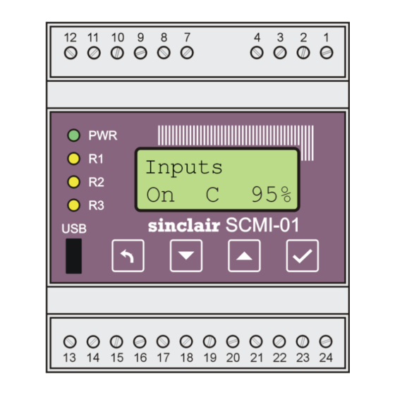
Fig. 2. Keys of the SCMI-01.5 module 4. SETTING THE MODULE The SCMI-01.5 control module can operate in one of the eight modes: Slave unit modes (Reg.U and Reg.M), Temperature control for cooling (Reg. T*), Temperature control for heating (Reg T+), Heating/cooling control depending on the status of the digital input H/C... - Page 7 Pos (desired temperature) is the target heating/cooling temperature modified by a delta (Del.heat or Del.cool) multiplied by a weighting coefficient of 0-100% determined by the value of the analogue voltage of 0-10V at the input of the SCMI-01.5 module. (When cooling, there is a C after the ▲ symbol).
- Page 8 3-minute delay is used to stabilize the operation. These delays are used usually when 30%, 45% (and also 75% for some units) of the compressor speed is achieved, and the SCMI-01.5 module takes this feature of the outdoor units into account.
-
Page 9: Using The Password To Set Up The Scmi Module
(to log on). If you try to change settings without logging, the display returns one level back. Under the default settings of the SCMI-01.5 control module, you can only change the display backlight and contrast without logging in. Once the module is connected to the USB port of the computer, you can use the USBCommunicator program to disable the password to set also the target temperature for heating and cooling. -
Page 10: Using The Password To Select The Outdoor Unit
If the correct password has been entered, it is possible to change the module settings for 30 minutes; then the operator is logged out. While the log-on state remains valid, menu Password is not displayed in the main setting menu of the SCMI-01.5 module. 4.2. Using the Password to Select the Outdoor Unit This function is used if the outdoor unit is not detected automatically. -
Page 11: Setting The Correction Limit For Cooling In The Txu Mode
Menu Del.cool is accessible only in the TxU mode, i.e. in the switched heating/cooling mode with temperature correction by voltage of 0-10V applied to the input of SCMI-01.5 module. This menu allows setting of limit temperature correction for cooling in the range of -20°C to +20°C;... -
Page 12: Setting The Correction Limit For Heating In The Txu Mode
4.6. Setting the Correction Limit for Heating in the TxU Mode The setting of the limit correction Del.heat for heating in the TxU mode and the operation of the SCMI-01.5 module in this mode is similar to that for cooling in the TxU mode; see Chapter 4.4. - Page 13 Slave unit controlled by an external voltage of 0-10V – Reg.U mode Outdoor unit compressor performance of 0-100% is controlled by the SCMI-01.5 module according to the DC voltage of 0-10V from an external device. The On/Off switch must be in the On position and, at the same time, the control voltage must be higher than 0.5V.
- Page 14 Slave unit controlled via Modbus – Reg.M mode Outdoor unit compressor performance is controlled by the SCMI-01.5 module according to the instructions received from an external device via a Modbus connected to the RS485 serial communication terminals. The wiring of the temperature sensors and the On/Off input is the same as in the previous mode.
- Page 15 The outdoor unit is controlled via the C-LINE high-voltage communication and the SCMI module is powered by 230V/50Hz mains voltage from the outdoor unit. Fig. 5. SCMI-01.5 control module in the autonomous supply air temperature control mode - 13 -...
- Page 16 The outdoor unit is controlled via the C-LINE high-voltage communication and the SCMI module is powered by 230V/50Hz mains voltage from the outdoor unit. Fig. 6. SCMI-01.5 control module in the switched heating/cooling mode - 14 -...
- Page 17 0 to 25.5 minutes (for this time, the pressure control is suppressed after the start-up of the unit) and compressor fixed speed from 0 to 100% can be set. Fig. 7. SCMI-01.5 control module in the autonomous pressure control mode affected by T2 temperature...
- Page 18 Del.heat multiplied by a weighting coefficient determined by the value of analogue voltage 0- 10V at the input of SCMI-01.5 module (voltage 0 to 10V corresponds to weighting coefficient 0 to 100% ). The thermometer T1 measures the temperature of the indoor unit heat exchanger.
- Page 19 The outdoor unit is controlled via the C-LINE high-voltage communication and the SCMI module is powered by 230V/50Hz mains voltage from the outdoor unit. Fig. 9. SCMI-01.5 control module in the autonomous supply air temperature control mode - 17 -...
-
Page 20: Setting The Evaporator Defrosting
4.8. Setting the Evaporator Defrosting This menu allows you to set the method and required parameters to control the defrosting of the evaporator of the indoor unit when running in the cooling modes. In the heating modes, the indoor unit heat exchanger operates as a condenser and defrosting of the outdoor unit evaporator is controlled by the outdoor unit. - Page 21 Setting the minimum defrosting period Press the ENTER key to enter the setting menu and use the ▼/▲ keys to select the Defrost menu. After opening this menu, select the Period menu. Defrost Period After opening this menu, the display shows: Period xx.x The xx.x represents the set minimum defrosting period in hours.
- Page 22 Setting the T1 temperature to start defrosting Press the ENTER key to enter the setting menu and use the ▼/▲ keys to select the Defrost menu. After opening this menu, select the Start menu. Defrost Start After opening this menu, the display shows: Start -xx.x The set temperature to stop!!! defrosting is displayed.
-
Page 23: Setting The Output Relays
Defrost 4.9. Setting the Output Relays The SCMI-01.5 module has three output relays with NO (normally-open) contacts, which can switch 230V/2A. Press the ENTER key to enter the setting menu and use the ▼/▲ keys to select the Outputs menu. After opening this menu, you can select the desired output: Relay 1 Setting the output relay R1 of the control module. - Page 24 Individual relays of the control module may have the following functions: ON/OFF The relay is controlled by the digital input On/Off of the control module. Compres. The relay is controlled identically with the outdoor unit compressor. Defrost The relay is controlled identically with the defrosting of the indoor unit evaporator.
-
Page 25: Setting The Control Constants
4.10. Setting the Control Constants This menu allows you to set the control constants of the SCMI-01.5 module. Press the ENTER key to enter the setting menu and use the ▼/▲ keys to select the Reg.cons menu. After opening this menu, you can select and set the control constants: Time con Setting the time constant of the module. -
Page 26: Settings The Display
4.11. Settings the Display This menu allows you to set the parameters of the display of the SMCI-01.5 control module. Press the ENTER key to enter the setting menu and use the ▼/▲ keys to select the Display menu. Settings Display After opening this menu, you can set the following display parameters: Backlit... - Page 27 Setting the language version Display Language < After opening this menu: Language Cesky < The current language version is followed by the sign <. When changing the language version, for example to English, use the ▼/▲ keys to select the desired English version: Language English Press the ENTER key to confirm this option.
-
Page 28: Setting The Scmi-01.5 Module Using The Computer
Multifunctional Tester. Fig. 10. Default settings of the SCMI-01.5 module With the actual version of the program, the SCMI-01.5 module has a number of new functions, which can be activated or whose parameters can be set by using only the USBCommunicator program. - Page 29 The desired temperature is then calculated from the set target temperatures corrected by the set values Del.cool and Del.heat multiplied by a weighting coefficient determined by the value of analogue voltage 0-10V at the input of SCMI-01.5 module (voltage 0 to 10V corresponds to the weighting coefficient 0 to 100%).
- Page 30 The RT Data button can be used to monitor the runtime data, similar to using an external Multifunctional Tester. Fig. 11. Display of runtime data of the SCMI-01.5 module For some outdoor units, the data of the compressor current consumption and output power are not available;...
-
Page 31: Error Messages
6. ERROR MESSAGES 6.1. Sensors and Communication Errors of the SCMI-01.5 Module During its operation, the SCMI-01.5 module tests the connection of the T1 & T2 resistance thermometers, and in the autonomous pressure control mode, it also tests the connection of the pressure sensor to the input 4-20mA. -
Page 32: Checking The Errors Recorded In Scmi-01.5 Module
Older error groups are displayed until no more are recorded. Err -3 No errors Press the ESC key to exit the error log viewing. In the documentation for the relevant Sinclair outdoor unit, the error codes are listed together with their interpretation of each error status. - 30 -... -
Page 33: Deleting The Error Logs In The Scmi-01.5 Module
6.3. Deleting the Error Logs in the SCMI-01.5 Module In the error viewing mode, you can delete the error records in the SCMI-01.5 module by simultaneously pressing ▼ and ENTER keys. After you press these keys, the display will show:... -
Page 34: Specifications
C-LINE high-voltage serial communication for controlling the outdoor unit RS485 serial communication for connecting Modbus or for monitoring the SCMI module using an external computer Service connector: USB, Mini-B connector 8. PACKAGE CONTENTS SCMI-01.5 communication module Temperature sensor Instruction manual (CD) - 32 -... -
Page 35: Overview Of The Scmi1.5 Unit Settings
9. OVERVIEW OF THE SCMI1.5 UNIT SETTINGS Menu Submenu/Option Range Default Note: +10,0°C Goal C Setting the desired temperature in the cooling mode -10 to +55 p. 8 +10,0°C Del.cool Limit of temperature change by voltage of 0-10V; only in TxU mode. -20 to +20 p. -
Page 36: Table Of Contents
Setting the SCMI-01.5 Module Using the Computer ............26 Error Messages ......................29 6.1. Sensors and Communication Errors of the SCMI-01.5 Module ......29 6.2. Checking the Errors Recorded in SCMI-01.5 Module ..........30 6.3. Deleting the Error Logs in the SCMI-01.5 Module ..........31 Specifications ........................32... - Page 37 United Kingdom www.sinclair-world.com This product was manufactured in China (Made in China). R E P R E S E N T A T I V E SINCLAIR Global Group s.r.o. Purkynova 45 612 00 Brno Czech Republic T E C H N I C A L S U P P O R T SINCLAIR Global Group s.r.o.
- Page 38 N O T E S...
- Page 39 N O T E S...
Need help?
Do you have a question about the SCMI-01.5 and is the answer not in the manual?
Questions and answers