Table of Contents
Advertisement
Quick Links
Instruction Manual
AVS-1
Advanced Ventilator System
Read instructions carefully before operating this device.
This device is not to be used for Human Life Support applications.
To avoid possible electrical shock, do not operate this device if is wet or has had liquids spilled onto it.
Service or calibration procedures should only be performed by qualified personnel familiar with the
electrical hazards of line-powered devices.
Ardmore PA 19003 U.S.A.
(610)642-7719
info@cwe-inc.com
©CWE 2023
www.cwe-inc.com
Advertisement
Table of Contents

Related Manuals for CWE AVS-1

Summary of Contents for CWE AVS-1
- Page 1 Instruction Manual AVS-1 Advanced Ventilator System Read instructions carefully before operating this device. This device is not to be used for Human Life Support applications. To avoid possible electrical shock, do not operate this device if is wet or has had liquids spilled onto it.
-
Page 2: Statement Of Warranty
LIFE SUPPORT POLICY Instruments manufactured by CWE, Incorporated are not authorized for use as critical components in human life support devices or systems. "Life support devices or systems", as used herein, are devices or systems whose failure to perform, whether through misuse, failure, or proper operation, can reasonably be expected to result in significant injury to the operator or subject persons. -
Page 3: Table Of Contents
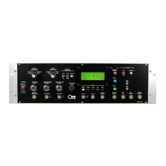
TABLE OF CONTENTS STATEMENT OF WARRANTY ..........................1 1.0 INTRODUCTION ..............................3 Figure 1: Model AVS-1 Front Panel ........................3 2.0 VENTILATOR CONNECTIONS AND SETUP ....................4 3.0 OPERATING CONTROLS ..........................4 Figure 2: AVS-1 LCD Display Panel ........................4 3.1 VOLUME CYCLED VENTILATION ........................ -
Page 4: Introduction
CO ventilation, and facilities for external control of ventilator function. The AVS-1 is capable of ventilating animals ranging from mice to cat-size by plugging in the appropriate external valve assembly. The AVS-1 is a flow-time ventilator. Inspiratory volumes are generated by gating a constant flow into the animal for a given time. -
Page 5: Ventilator Connections And Setup
AVS-1 Instruction Manual 2.0 VENTILATOR CONNECTIONS AND SETUP Setting up the AVS-1 is straightforward. The unit may be rack mounted, or can be placed on a benchtop. For basic ventilator functioning, the following connections are required: Plug the provided power cord into a grounded power outlet. The power supply is universal, so 115V/60Hz or 230V/50Hz mains power is usable. -
Page 6: Volume Cycled Ventilation
AVS-1 Instruction Manual 3.1 VOLUME CYCLED VENTILATION For volume-cycled ventilation, set , and START INSPIRATION CLOCK STOP . This means that a free running clock will start the inspiratory INSPIRATION TIME cycle, and an elapsed time will end it. First, set the... -
Page 7: Neural Cycled Ventilation
AVS-1 Instruction Manual 3.4 NEURAL CYCLED VENTILATION A unique feature of the AVS-1 Ventilator is the ability to synchronize ventilation to Phrenic (or other) nerve activity. Phrenic activity can be used to start and stop, or just to start inspiration. For proper triggering, a Moving Average of the Phrenic activity is required as the input signal. -
Page 8: Auto Mode
This is the MONITOR actual signal used by the controller. Locate the CO trimpots on SPAN AND ZERO the front panel of the AVS-1. These are used to adjust the gain and offset of the raw capnograph signal. ©2023 CWE, Inc. -
Page 9: Triggering From External Sources
AVS-1 Instruction Manual While observing the oscilloscope trace, adjust the CO trimpots SPAN AND ZERO so that the peak end-expiratory signal falls within the range 0 - 5V. The actual gain and position is not important; just be sure the peak CO will always fall within 0 - 5V. -
Page 10: Special Lcd Display Functions
AVS-1 Instruction Manual and/or switches to to activate the external INSPIRATION STOP INSPIRATION inputs. NOTE: The External Control Inputs are also accessible on the DATA on the rear panel. PORT 3.7 SPECIAL LCD DISPLAY FUNCTIONS Besides the basic ventilator parameters and settings described earlier, the LCD display panel provides important information regarding ventilator operation (see Figure 2). -
Page 11: Monitor Outputs
Its range is +5V, with PRESSURE OUT zero volts equal to zero pressure. The scale of this output is 100mV/cmH 3.9 MANUAL CONTROL OF VENTILATION The AVS-1 can be operated completely manually, if desired. The switch HOLD causes inspiration to be suspended indefinitely. The... -
Page 12: Data Interface
3.10 DATA INTERFACE on the rear panel provides access to a number of external control DATA PORT functions, and internal monitoring signals. The function of these connections on the AVS-1 is described below. Figure 3: AVS-1Data Port connections AVS-1 Connections: DATA PORT SERIAL PORT (GND, RX, TX) —... -
Page 13: Ordering Information
AVS-1 Instruction Manual 4.0 ORDERING INFORMATION PART N MODEL DESCRIPTION 12-07000 AVS-1 Ventilator with one Valve Assembly (CTP-VA-1 or CTP-VA-3) 12-04000 CTP-VA-1 Solenoid Valve Assembly, mouse to Guinea pig size 12-05000 CTP-VA-3 Solenoid Valve Assembly, cat to small monkey size... - Page 14 AVS-1 Instruction Manual Figure 4: External Valve Assembly connection diagram ©2023 CWE, Inc.
-
Page 15: Appendix 1: Tidal Volume Vt) Vs. Body Weight Charts
AVS-1 Instruction Manual APPENDIX 1: TIDAL VOLUME VT) VS. BODY WEIGHT CHARTS Tidal Volume Chart Breaths per minute 40 50 300 400 500 1000 Body Weight (g) Tidal Volume Chart 1000 Breaths per minute 5 6 7 8 9 40 50 Body Weight (kg) ©2023 CWE, Inc. -
Page 16: Appendix 2: Typical Ventilator Settings For Rodents
AVS-1 Instruction Manual APPENDIX 2: TYPICAL VENTILATOR SETTINGS FOR RODENTS Flow Weight (g) VT (ml) (bpm) (ml/m) TI (s) I:E (%) 0.15 0.200 0.61 0.267 1.22 0.300 2.15 0.400 3.08 0.480 1000 6.20 0.533 2500 15.64 1369 0.686 Note: Settings above are suggested guidelines. These are based on the following equations, with slight modifications owing to the difference between spontaneously breathing animals vs.
Need help?
Do you have a question about the AVS-1 and is the answer not in the manual?
Questions and answers