
Summary of Contents for Nobel Avantis Micro
- Page 1 The Avantis Micro The Avantis Micro Control Panel Installation Guide This document contains confidential information and should not be distributed without the express permission of Nobel Fire Systems...
-
Page 2: Safety Statement
Introduction The MICRO control panel can be installed as a standalone suppression panel with minimal signalling and configurability. It can also be placed in a digitally addressable MODBUS network alongside a TI to form a system which offers advanced reporting, ease of use and a higher level of configurability. The MICRO has a single zone detection circuit and two fully monitored suppression outputs (each of which can operate 3 x Stat-X units or 1 NFS Gas Generator). -
Page 3: Cable Specifications
Cable Specifications All screw terminals are capable of cable cross section size of 0.05mm - 1.5mm . The following cables are recommended to be used in this system: • Micro to Micro Belden Screened 4 Core. • Mains power supply FP200 1.5mm 3 Core. -
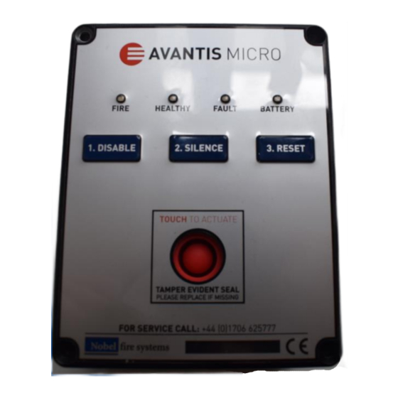
Page 5: Controls And Operation
The user/operator of the Micro control panel must be aware of the risks involved with misuse or misunderstanding of this device i.e. accidental discharge of a fire suppression system and the costs incurred for system recharge. Contact local Nobel Fire Systems distributor if there is any confusion. Unlocking the Micro The MICRO’s keys (except the silence button) are locked by default. - Page 6 Actions & Tests Disable/Enable/Re-Enable When the Micro is packaged for dispatch, it is set to disable as default. In this dormant state, the healthy LED will not flash, and the fault and fire relays will not operate. The only LED that will be illuminated will be the Battery LED, providing the batteries have been fitted properly.
-
Page 7: Commissioning Tests
Commissioning Tests Detection In access level 2, disable each Micro before the detection circuitry can be tested. Locate the terminated end of the linear heat detection cable (LHDC) which will be fitted into a termination block. The two conductors of the L.H.D.C must be shorted together using a metal conductor. If successful, the Fire LED will illuminate and the buzzer and sounder (if connected) will sound continuously.
Need help?
Do you have a question about the Avantis Micro and is the answer not in the manual?
Questions and answers