
Subscribe to Our Youtube Channel
Summary of Contents for PicoQuant PicoHarp 330
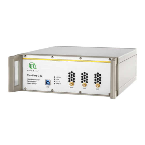
- Page 1 PicoHarp 330 High Resolution Event Timer Multichannel Time–Correlated Single Photon Counting and Time Tagging System with USB Interface User's Manual and Technical Data Version 1.0.0.0...
- Page 2 Acknowledgments When the PicoHarp 330 software is used under Linux it uses Libusb to access the PicoHarp 330 USB devices. Libusb is licensed under the LGPL which allows a fairly free use even in commercial projects. For details and precise terms please see http://libusb.info.
-
Page 3: Table Of Contents
3.5. Hardware Installation........................... 3.5.1. Electrical Connection........................3.6. Installation Troubleshooting......................... 3.7. Uninstalling the Software........................Software Overview............................4.1. Starting the PicoHarp 330 Software....................4.2. The Main Window..........................4.3. The Toolbar............................4.4. The Control Panel..........................4.5. The Axis Panel............................ 4.6. The Trace Mapping Dialog........................ - Page 4 6.5. Axis Panel............................6.5.1. Time Axis Group.......................... 6.5.2. Count Axis Group........................6.6. Trace Mapping Dialog......................... 6.7. General Settings Dialog........................6.8. About PicoHarp 330… Dialog......................6.9. Title and Comment Editor........................6.10. Print Preview Dialog.......................... Problems, Tips & Tricks..........................7.1. Basic Pitfalls............................7.2.
- Page 5 PicoQuant GmbH PicoHarp 330 Software V. 1.0.0.0 8.3.3. Indicators............................ 8.4. Using the Software under Linux......................Page 5...
-
Page 6: Introduction
The resulting histogram represents the fluorescence decay. Although fluorescence lifetime analysis is a great field of application for the PicoHarp 330, it is in no way restricted to this task. Other important applications are e.g. Quantum Optics, Quantum Cryptography (QC) Time–Of–Flight (TOF) and Optical Time Domain Reflectometry (OTDR) as well as any kind of coincidence correlation. -
Page 7: Primer On Time-Correlated Single Photon Counting
PicoQuant GmbH PicoHarp 330 Software V. 1.0.0.0 2. Primer on Time–Correlated Single Photon Counting In order to make use of a powerful analysis tool such as time–resolved fluorescence spectroscopy, the time de- pendent intensity of the emitted light must be recorded. While in principle it could be attempted to record to record the intensity decay of the signal from a single excitation / emission cycle, there are practical problems that prevent such a simple solution in most cases. -
Page 8: Count Rates And Single Photon Statistics
TCSPC electronics such as the PicoHarp 330 support multi-stop (i.e. recording more than one photon per excitation cycle) and can reach count rates up to 80 Mcps. With the PicoHarp 330 and modern detectors such as Hybrid Photodetectors (HPD) count rates at this upper limit can be collected. -
Page 9: Timing Resolution
(phase noise). However, the contribution of the electron- ics to the total timing error is usually small. For the high resolution device PicoHarp 330 the random jitter of a time difference measurement is typically only 3 ps rms. -
Page 10: Photon Counting Detectors
PMTs. Good but also expensive MCPs can achieve tim- ing uncertainties as low as 25 ps. In this respect, microchannel plates are a good match for the PicoHarp 330 but they are quite limited in permitted count rate and provide lower sensitivity towards the red end of the spec- trum compared to suitably optimized detectors. -
Page 11: Hybrid Photodetectors
600 ps down to which they can be separated. This results in en effective dead time that is very well matched to that of the PicoHarp 330 so that the method of rapidFLIM can be implemented very efficiently. - Page 12 The PicoHarp 330 uses one such circuit in each input channel and one for the sync input. They independently work on each input signal and provide picosecond arrival times that can then be pro - cessed further, with a lot more options than in conventional TCSPC systems.
- Page 13 2) Changing between slow and fast excitation sources requires reconnecting to different inputs. The PicoHarp 330 is radically different in this respect, as it allows to work in forward start stop mode, even with fast lasers. This is facilitated by two design features: 1) Independent operation of the TDCs of all channels, and 2) a programmable divider in front of the sync input.
- Page 14 50 Ω coax cable. When using the PicoHarp 330 in combination with the PDL 800– B or a similar PicoQuant laser driver, a 10 dB attenuator can be inserted directly at the sync output of the laser driver.
- Page 15 PicoQuant GmbH PicoHarp 330 Software V. 1.0.0.0 Page 15...
-
Page 16: Further Reading
12. Isbaner S., Karedla N., Ruhlandt D., Stein S.C., Chizhik A., Gregor I., Enderlein J.: Dead-time correction of fluorescence lifetime measurements and fluorescence lifetime imaging. Opt. Express 24(9):9429-45 (2016) doi: 10.1364/OE.24.009429 13. Bibliography listing all publications with work based on PicoQuant instruments http://www.picoquant.com/scientific/references 14. Web page of the PicoQuant TCSPC and time tagging devices https://www.picoquant.com/products/category/tcspc-and-time-tagging-modules... -
Page 17: Hardware And Software Installation
Important: The hardware and software of the predecessor product PicoHarp 300 is significantly different from that of the new PicoHarp 330. There is no software compatibility across the two products. Please do not confuse the two products. The PicoHarp 300 has its own manual and its own software. Here we cover only the Pico- Harp 330. -
Page 18: Software Installation
For the driver installation, it is needed in any case. Installing as administrator has the benefit that you can install the software for all users on that computer even if they have limited access rights. The PicoHarp 330 soft- ware will maintain individual settings for each user in the Windows registry. -
Page 19: Hardware Installation
USB 2.0 or super speed USB 3.x connectors. The latter can usu- ally be identified by their blue color. The PicoHarp 330 will not work with a USB 1.x connection. However, all cur- rent PCs should readily provide USB 3.0 connectivity. -
Page 20: Installation Troubleshooting
Should the software appear sluggish during measurements it may be because the USB connection is running only at USB 2.0 speed. The USB LED on the front panel of the PicoHarp 330 will then show yellow. At proper USB 3.0 superspeed it will light up green. Check your USB cable and try other USB ports of the PC to get this fixed. - Page 21 PicoQuant GmbH PicoHarp 330 Software V. 1.0.0.0 Note that uninstallation of the data acquisition software does not uninstall the device driver. This is because other software may still need it. You can delete the driver software from within Device Manager.
-
Page 22: Software Overview
It is possible to use up to eight PicoHarp 330 devices on one PC. If multiple devices are installed then the first instance of the software will connect to the first device, the second to the second device and so on. Each of the PicoHarp 330 software instances displays the serial number of the device it uses. - Page 23 Harp 330. The rightmost area of the status bar indicates if the <Caps> and <NumLock> keys are latched down. When the PicoHarp 330 software is running with functional hardware it continuously collects informa- tion about the input signals and the current acquisition settings. If these settings together with the in - put rates indicate possible errors, the software will display a warning icon in the status bar.
-
Page 24: The Toolbar
Software V. 1.0.0.0 4.3. The Toolbar The toolbar is displayed across the top of the PicoHarp 330 software main window, below the menu bar. The toolbar provides quick mouse access to frequently used commands and tools. Note that some buttons may be grayed out (disabled) depending on the state of the hardware. -
Page 25: The Control Panel
4.4. The Control Panel The PicoHarp 330 control panel is a dialog box for setting the parameters for hardware adjustment and data ac- quisition. It is implemented as a ‘non–modal’ dialog box, i.e. it does not have to be closed before the main win- dow can continue to operate. - Page 26 Windows registry and retrieved during the next program start. The registry settings are stored separately per user. When a PicoHarp 330 data file is loaded, the control panel settings will change to reflect the settings stored in that file.
-
Page 27: The Axis Panel
PicoQuant GmbH PicoHarp 330 Software V. 1.0.0.0 4.5. The Axis Panel The axis settings panel is a dialog box for setting the axis range for the histogram display in the main window. It is implemented as a ‘non–modal’ dialog box, i.e. it does not have to be closed before the main window can con- tinue its operation. -
Page 28: The Trace Mapping Dialog
4.6. The Trace Mapping Dialog The PicoHarp 330 software can record and store histograms in up to 512 data blocks in memory and files. Out of these, up to 16 curves can be displayed at the same time. It may seem odd that only 16 traces can be dis- played. -
Page 29: Other Dialogs
PicoQuant GmbH PicoHarp 330 Software V. 1.0.0.0 4.7. Other Dialogs In order to keep this manual readable, the dialogs described here in the overview chapter are limited to the most important ones the reader should know about before starting practical work with the software. Additional dialogs will be described implicitly in the following sections in the context of specific measurement tasks. -
Page 30: Specific Measurement Tasks
2 first. Also consider the literature listed there. In order to acquire any data, the input channels and the sync input of the PicoHarp 330 must be set to match their electrical input signals. The PicoHarp 330’s sync and input channels are all designed identically. The Pico- Harp 330 software allows the configuration of all inputs to either use a CFD or a simple comparator (edge trig- ger). - Page 31 If the signal is satisfactory, connect the source to the sync input and start the PicoHarp 330 software if it is not yet running. A detector signal (CH1, CH2, ...) is not required at this point but it does no harm if it is also con - nected.
- Page 32 Preliminary adjustments can actually be done with uncorrelated light, e.g. daylight. To protect your detector, use strongly attenuated light, even when the detector is off. Start the PicoHarp 330 software and open the Control Panel. Look at the Control Panel section for the chosen channel. Select Edge Trigger and initially set the trigger level to half the expected pulse height and set the trigger edge (rising=1, falling=0) to match the lead - ing edge of your detector pulses.
- Page 33 During the set-up process you should pay attention to the warning icon that may appear at the bottom right of the main window. When the PicoHarp 330 software is running with functional hardware it con- tinuously collects information about the input signals and the current acquisition settings. If these set- tings in combination with the input rates indicate possible errors, the software will activate the warning icon.
-
Page 34: Setting Up And Running Interactive Measurements
5.2. Setting Up and Running Interactive Measurements The primary mode of operation of the PicoHarp 330 software is interactive histogramming. This is what the main window of the software is dedicated to. The user can set up measurement parameters, start measurements and immediately see histogram data on the screen. -
Page 35: Time Tagged Mode Measurements
If it is intended to make use of the full TTTR throughput of a PicoHarp 330 (up to 90 Mcps via USB 3) then the hard disk must be able to handle sustained write rates of 360 MBytes/s. -
Page 36: T3 Mode
Harp 330 software provides a real-time FCS correlator for preview during a T2 mode measurement (see section 5.3.7). Other types of real-time processing must be implemented by custom software. The PicoHarp 330 soft- ware installation provides demo programs to show how T2 mode files can be read by custom software (see the folder filedemo under the chosen software installation folder). -
Page 37: Running A Basic Tttr Mode Measurement
The file name is shown in red if the file already exists. The button with the file icon will open a standard Windows file dialog. You can select an existing file or choose a new name. The PicoHarp 330 TTTR mode files have the extension ".ptu". -
Page 38: External Markers
As outlined above, TTTR data collection at high rates is a demanding real-time streaming process. The hard- ware and software must ensure not to lose any data. In order to implement this efficiently the PicoHarp 330 soft- ware employs multiple threads (concurrent CPU processes). A first thread continuously reads the PicoHarp 330‘s hardware FIFO and puts the retrieved data in a software queue. -
Page 39: Using Tttr Mode Data Files
T3 mode data. The time-tag informa - tion will not be used here. The PicoHarp 330 software will recognize that you are loading a T3 mode file and how many records are contained in it. - Page 40 PicoQuant GmbH PicoHarp 330 Software V. 1.0.0.0 in columns A and B, respectively, will be aggregated and used in the corresponding correlation channel. If your selection is empty, the heading of the section Cor(Ax,Bx) will turn red to indicate the problem. If you proceed anyway you will get error messages upon start.
-
Page 41: Tttr Mode Measurements With Event Filtering
PicoQuant GmbH PicoHarp 330 Software V. 1.0.0.0 log stage. A higher number of subsamples increases the resolution of the correlation curve. Calculating more points is more time consuming and therefore may lead to lower count rate limits that can be handled. In this case you may get FIFO overruns. - Page 42 PicoQuant GmbH PicoHarp 330 Software V. 1.0.0.0 In such systems, the time offset between the channels can be arbitrarily shifted in hardware and/or postprocess- ing. Consider a time offset Δt even larger than the one shown in the sketch above. Here, a photon from an ear- lier pair in CH1 (i –...
- Page 43 Generator G1 provides pulses at a frequency of 10 MHz. By means of a 50 Ohms power splitter (aka reflection free T-pad) identical pulse trains are fed to the PicoHarp 330’s sync input and photon timing input channel 1. Generator G2 provides an independent periodic pulse train of 1 MHz that is fed to the PicoHarp 330’s photon timing input channel 2.
- Page 44 We use T3 mode because it is functionally related to histogramming mode, in that it also assumes a typically periodic sync signal and, more important here, the PicoHarp 330 software permits loading T3 mode files directly into the histogram display. We could do the experiment by way of a regular TTTR mode measure- ment (See section 5.3.4) but for didactic purposes we shall do it through the dialog for Filtered TTTR mode.
- Page 45 PicoQuant GmbH PicoHarp 330 Software V. 1.0.0.0 Most prominent on the top there is a pair of radio buttons for T2 versus T3 mode. It is important to make this se- lection first, as it will determine the permitted filter settings for the sync channel.
- Page 46 USB. Recall that the PicoHarp 330 has an extremely high input bandwidth: each channel can in principle capture events at up to 1.47 GHz. Despite a sophisticated FIFO buffering scheme (see section 5.3.2) combined over the instru- ment’s channels this high rate cannot be sustained for long in internal processing and USB transfer.
- Page 47 PicoQuant GmbH PicoHarp 330 Software V. 1.0.0.0 As expected, because the filter was disabled, we obtain histograms exactly as in our initial test in histogramming mode. Having completed this basic test we can now return to the filtered TTTR mode dialog and proceed to a filtered measurement.
- Page 48 If you open a second in- stance of the PicoHarp 330 software you can leave the first instance in TTTR mode and use the second in- stance as a file viewer.
- Page 49 PicoQuant GmbH PicoHarp 330 Software V. 1.0.0.0 The effect of the filter can now be seen very nicely. First observe the red trace (Generator G2 on Channel 2). The histogram is now empty everywhere, except in the vicinity of the blue peak. The remaining slice of the red trace is exactly the chosen filter range of 4 ns on either side of the blue peak from G1.
- Page 50 PicoQuant GmbH PicoHarp 330 Software V. 1.0.0.0 Performing a real measurement into the file ‘Filtered-Inverted.ptu’ and loading the file back into the histogram display we can nicely visualize the inverse filter operation. Page 50...
- Page 51 PicoQuant GmbH PicoHarp 330 Software V. 1.0.0.0 The part of the red histogram that was previously kept in is now punched out and the blue peak is diminished much less, according to the ratio of removed versus unremoved events in the red histogram.
-
Page 52: Sequence Mode
Time-Resolved Excitation/Emission Spectra (TRES), ideally with automated wavelength scan and TCSPC data collection under full software control. In order to facilitate a generic range of such applications with great flexibilty, the PicoHarp 330 software pro- vides an automated sequence (SEQ) measurement mode. This mode first of all allows software controlled repe- tition of a histogram mode measurement. - Page 53 The SEQ measurement is selected in the PicoHarp 330 control panel. You need to use the selection box for the measurement mode to select SEQ mode (instead of OSC or INT).
- Page 54 FluoPlot is provided on your software installation media. Just run FluoPlotSetup.exe from there. If you received your PicoHarp 330 software by download or email you may need to request FluoPlot separately. Note that the program requires a graphics processing unit with support for OpenGL version 1.5 or higher. Speedy handling of large data files requires sufficient system memory.
-
Page 55: Multi-Channel Scaling
Software V. 1.0.0.0 5.5. Multi-Channel Scaling In contrast to classic TCSPC systems (based on TACs), the sync and the signal channels of the PicoHarp 330 are completely independent. This makes it possible to allow multi-stop measurements, i.e. the detection of multi- ple photons between two subsequent START signals. -
Page 56: Controls And Commands Reference
Close Button Scroll bars Displayed at the right and bottom edges of the PicoHarp 330 window if a certain minimum window size is reached. The scroll boxes inside the scroll bars indicate your vertical and horizontal location in the display area. - Page 57 PicoQuant GmbH PicoHarp 330 Software V. 1.0.0.0 Restore command Use this command to return from a maximized or minimized window to the previous size. Note: The command is only available for already maximized or minimized windows. Shortcut Mouse: Click the maximize button on the title bar;...
-
Page 58: Menus
Use this command to open an existing histogram file. All control panel settings will also be restored. You can also open PicoHarp 330 histogram files (*.phu) by double clicking them or dragging them onto the PicoHarp 330 icon. You can revert to a blank histogram and default control panel settings with the New command. You can also select *.ptu files for loading as histogram data but they must be T3 mode files. - Page 59 Use this command to save the current histogram data to a file with current name and directory. When you save a histogram for the first time, PicoHarp 330 displays the Save As… dialog box so you can name your file. This command is unavailable if a measurement is running.
-
Page 60: Edit Menu
Choose the number that corresponds with the file you want to open. Shortcuts Keys: <Alt>+F 1 <Alt>+F 2 <Alt>+F 3 <Alt>+F 4 Exit command Use this command to end your PicoHarp 330 session. Save your data before exiting. Shortcuts Mouse: Click the close button on the title bar. Keys: <Alt>+<F4> <Alt>+F X 6.2.2. -
Page 61: View Menu
Status Bar command Use this command to display or hide the status bar at the bottom of the PicoHarp 330 main window. The left pane of the status bar describes the action to be executed by a menu item or toolbar button as the mouse pointer hovers over it. -
Page 62: Help Menu
Request Support Provides support details and access to the support website. About PicoHarp 330 Displays version information of the PicoHarp 330 software. 330… Note: Online help (context help) on most functions, dialogs, control items etc. is available via the F1 key. - Page 63 If your setup is not working at all, provide at least the serial number of your PicoHarp 330 and a precise description of the installation environment and the observed issues, including the exact wording of any occurring error messages.
-
Page 64: Toolbar
When you choose the Context Help button, the mouse pointer will change to an arrow with question mark. If you then click somewhere in the PicoHarp 330 window, such as on another toolbar button, the help topic associated with it will be shown. - Page 65 "Show" boxes to display a curve. Select the number of the memory block you wish to map the individual display curve to. Choose the active memory block you wish to use for the next measurement in the PicoHarp 330 con- trol panel.
-
Page 66: Control Panel
When you load a PicoHarp 330 data file the settings of the control panel will change according to the settings in that file. -
Page 67: Inp.chan 1 And 2
The settings in these dialog tabs configure the behavior of the input channels. See section 5.1 “Setting Up the Input Channels“ to get started. The PicoHarp 330 can have up to two usable input channels, dependent on how many were purchased. Upgrades can be purchased later. Dependent on how many usable channels the device has, some control elements for the channels may remain disabled. - Page 68 PicoQuant GmbH PicoHarp 330 Software V. 1.0.0.0 EdgeTr. / CFD radio buttons Here the trigger input circuit of the channel can be configured for Edge Trigger versus Constant Fraction Dis - criminator (CFD). The latter is useful for detectors with fluctuating pulse height but allows only negative going pulses.
-
Page 69: Acquisition
Trc./Block trace color indicator, edit box and spin control The PicoHarp 330 software can measure and store histograms in up to 512 memory blocks. Out of these, up to 16 curves can be displayed and one "active block" can be used for measurements. Choose the active memory block you wish to use for the next measurement here. - Page 70 PicoQuant GmbH PicoHarp 330 Software V. 1.0.0.0 on the trace color indicator. The color indicator shows the trace color the chosen block is currently mapped to. If it is a solid square, the curve is mapped and shown. If it is mapped but not shown, the indicator shows a small striped square.
-
Page 71: Axis Panel
PicoQuant GmbH PicoHarp 330 Software V. 1.0.0.0 6.5. Axis Panel The controls of the Axis Panel are used to customize the main window's histogram display. All mouse actions on the spin controls on this dialog result in instant modification of the display. If you choose to alter the values in the edit fields by keyboard, you have to finalize your changes by pressing <Enter> ... -
Page 72: Trace Mapping Dialog
6.6. Trace Mapping Dialog The PicoHarp 330 software can measure and store histograms in up to 512 memory blocks. Out of these, up to 16 curves can be displayed at the same time. The trace mapping dialog is used to select the curves to display. -
Page 73: About Picoharp 330
PicoHarp 330. Also note that any disconnection from or inter- ruption of the external clock will cause the PicoHarp 330 to fail and report an error. To recover from this error state the device must be re-initialized after the clock source is stable again. - Page 74 PicoQuant GmbH PicoHarp 330 Software V. 1.0.0.0 Next Page Preview the next printed page. Prev Page Preview the previous printed page. One Page / Two Page Preview one or two printed pages at a time. Zoom In Take a closer look at the printed page.
-
Page 75: Problems, Tips & Tricks
7. Problems, Tips & Tricks 7.1. Basic Pitfalls The hardware settings in the PicoHarp 330 software are retrieved to the current settings upon loading an exist- ing measurement file. This is a convenient feature most users like because it easily permits repeating a mea- surement with identical settings. -
Page 76: Warm-Up Period
If your system is not functional at all, the minimum information you must provide for support is the serial number of your PicoHarp 330. It can be found at the back of the housing. There may be other relevant... - Page 77 At our web–site we maintain a large bibliography of publications related to our instruments. It may serve as a reference for you and other potential users. See http://www.picoquant.com/scientific/references. Please submit your publications for addition to this list.
-
Page 78: Appendix
8. Appendix 8.1. Warnings When the PicoHarp 330 software is running with functional hardware it continuously collects informa- tion about the input signals and the current acquisition settings. If these settings along with the input rates indicate possible errors, the software will indicate this by showing a warning icon. - Page 79 PicoQuant GmbH PicoHarp 330 Software V. 1.0.0.0 Warning Histo Mode T2 Mode T3 Mode WARNING_INPT_RATE_TOO_HIGH The overall pulse rate at the input channels is higher than 85 MHz (USB 3.0 connection) or higher than 9 MHz (USB 2.0 connection). This is close to the throughput limit of the present USB connec- √...
- Page 80 √ occur typically only at very high count rates or during very intense bursts of events. WARNING_USB20_SPEED_ONLY This warning appears when the PicoHarp 330’s USB connection is running only at USB 2.0 speed. For proper performance it should √ √...
-
Page 81: Data File Formats
330 data files still carry a format version number, which is now called content version and currently has the string value “1.0”. In order to identify a PicoHarp 330 data file as a file created by and to be used by the na- tive PicoHarp 330 software there is a tag assured content which begins with the string “PicoHarp 330“. - Page 82 It is worth noting that the actual TTTR record data following the file header corresponds directly to the raw data obtained with custom programs using the PicoHarp 330 programming library. Page 82...
-
Page 83: Hardware Technical Data
PicoQuant GmbH PicoHarp 330 Software V. 1.0.0.0 8.3. Hardware Technical Data 8.3.1. Specifications All information given here is reliable to our best knowledge. However, no responsibility is assumed for possible inaccuracies or omissions. Specifications and external appearance are subject to change without notice. - Page 84 PicoQuant GmbH PicoHarp 330 Software V. 1.0.0.0 two signals each to a separate input channel. The differences of the measured pulse arrival times are then calculated along with the corresponding standard deviation. This latter value is the rms jitter or timing uncertainty of start-stop measurements. However, calculating such time differences requires two measurements.
-
Page 85: Connectors
The inputs for the photon detector signals and the sync signal are SMA connectors located on the front panel of the PicoHarp 330. They are labeled SYNC, CH1, and CH2. The inputs are terminated with 50 Ohms internally. Use quality 50 Ohms coax cables with appropriate connectors. For interfacing to BNC connectors use standard adapters. - Page 86 PicoQuant GmbH PicoHarp 330 Software V. 1.0.0.0 CTRL Connector – Pin numbering scheme CTRL Connector – Default Pin Assignments Pin# Name Purpose/Description GPIO 0 TTL in marker 1 input GPIO 1 TTL in marker 2 input GPIO 2 TTL in...
- Page 87 REF OUT provides an industry standard 10 MHz clock output phase locked to the PicoHarp 330’s internal clock, e.g., for the REF IN of another PicoHarp 330. Once the other PicoHarp 330 has locked its internal PLL to this signal the clocks of the two devices will not drift apart.
- Page 88 = PLL locked yellow = reconfiguring, PLL not yet locked = PLL not locked This is particularly relevant when an external clock is used. The LED will then indicate if the PicoHarp 330 has actually locked itself to that frequency. ERROR...
- Page 89 PicoHarp 330 Software V. 1.0.0.0 8.4. Using the Software under Linux The PicoHarp 330 software can also be used under Linux (x86-64 platform only). This requires that Wine is in- stalled (see http s ://www.winehq.org ). You can run the regular software setup as explained in section 3.4. In- stead of installing a device driver, running under Linux with Wine requires that you have Libusb 1.0 installed...
Need help?
Do you have a question about the PicoHarp 330 and is the answer not in the manual?
Questions and answers