Table of Contents
Advertisement
Quick Links
Ridder – Drive Systems
Lorentzstraat 38
3846 AX Harderwijk
PO Box 360
3840 AJ Harderwijk
the Netherlands
RW800-SD
T +31 (0)85 237 3000
E info@ridder.com
I ridder.com
RW-SD Motor Gearboxes 1-phase
RW70-SD
RW140-SD
RW45-SD
Product Manual
Ridder SmartDrive
Original product-manual
265002EN - 2024.05 - V01
RW240-SD
RW400-SD
RW600-SD
Advertisement
Table of Contents

Summary of Contents for Ridder Drive Systems SmartDrive RW70-SD
- Page 1 Ridder – Drive Systems Lorentzstraat 38 3846 AX Harderwijk T +31 (0)85 237 3000 PO Box 360 E info@ridder.com 3840 AJ Harderwijk I ridder.com the Netherlands Product Manual Ridder SmartDrive RW-SD Motor Gearboxes 1-phase Original product-manual 265002EN - 2024.05 - V01 RW70-SD RW140-SD RW800-SD...
-
Page 2: Table Of Contents
TABLE OF CONTENTS 1. GUIDELINES, STANDARDS AND CONDITIONS 1.1 Applicable guidelines and standards 1.2 Approved personnel 1.3 Warning about discouraged use 1.4 Special tools and equipment 1.5 Warranty provisions 1.6 Open Source Software (OSS) 2. SAFETY, PRECAUTIONS AND SYMBOLS 2.1 Signal words, instructions and warnings 2.2 Precautions and safety instructions 2.3 Residual risks 2.4 Symbols and abbreviations... -
Page 3: Guidelines, Standards And Conditions
12. SETTINGS 12.1 Feedback settings 12.1.1 Setpoint: full feedback (linear) 12.1.2 Reversed feedback 12.1.3 Feedback type 12.2 Auxiliary contacts settings 12.2.1 Fault contact 12.2.2 Setpoint: enabled auxiliary contact 12.2.3 Frequency limiter 12.3 More settings 12.3.1 Change screen orientation 12.3.2 Change language 12.3.3 Back to factory settings 13. -
Page 4: Approved Personnel
If this equipment does cause harmful interference to radio or television reception, which can be determined by turning the equipment off and on, the user is encouraged to try to correct the interference by one or more of the measures that follow: • Reorient or relocate the receiving antenna. -
Page 5: Special Tools And Equipment
1.4 Special tools and equipment Bluetooth To use Bluetooth the special tools and equipment that follow are necessary: ① A mobile device with SmartPhone functionality ② The Ridder SmartDrive App. Go to Google Play Store or Apple App Store for download and setup. -
Page 6: Safety, Precautions And Symbols
2. SAFETY, PRECAUTIONS AND SYMBOLS 2.1 Signal words, instructions and warnings Signal words (ISO 3864-2) This product manual contains safety instructions with different signal words. The list that follows gives the risk levels and possible effects of each signal word. Suggestion to perform an operation more effectively. -
Page 7: Precautions And Safety Instructions
2.2 Precautions and safety instructions Precautions GENERAL A system can be dangerous. Safety precautions and instructions are important. • If these precautions cannot be obeyed, then use warnings. • The responsibility for precautions and warnings lies with the installer of the system. Refer to the, local or national, laws and regulations of the country if a certification (mark) is necessary. -
Page 8: Residual Risks
• IF NECESSARY: For a fail-safe function install redundant safety systems to prevent that loads or system parts fall uncontrolled. Install (if necessary) protection from system parts that move. Obey the applicable national and/or local standards and guidelines of the related type of operated system. -
Page 9: Symbols And Abbreviations
2.4 Symbols and abbreviations This section tells about used symbols and abbreviations in this manual. The table that follows gives the descriptions. Symbol Description Symbol Description BU cover Neutral wire BU circuit board “normally closed” BU closing cover “normally open” BU locking system Open Source Software PU circuit board... -
Page 10: Product Details
3. PRODUCT DETAILS 3.1 Identification EXAMPLE This product manual is only applicable to: • Ridder SmartDrive RW-SD Motor Gearboxes 1-phase • Serial numbers from 202.000.000 • Item numbers from 600000. Certification number “Industry Canada” Ê Identification FCC product certification Identification is possible from the sticker on the location shown (A3). Refer to the explanation that follows on how to read the information. -
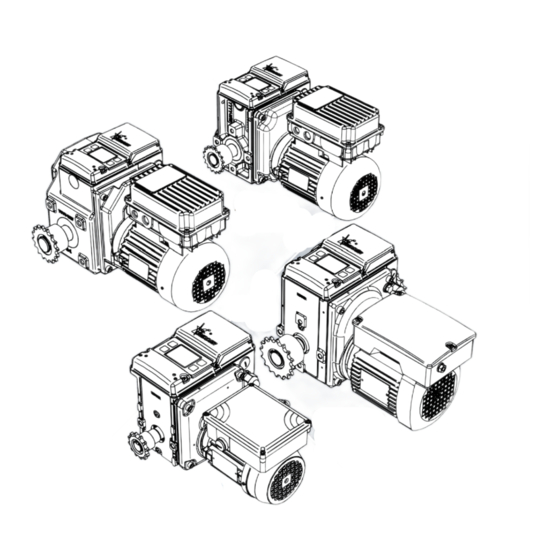
Page 11: Description
3.2 Description RW-SD motor gearboxes are drive units to operate systems in greenhouses, livestock houses, crop- storage buildings and such. The RW-SD motor gearboxes are applicable at ambient temperatures between 0 and 60 °C. RW-SD motor gearboxes have a self-braking worm-gear transmission which stops the drive unit (worm shaft) when not operated and then locks the output shaft. - Page 12 RW45-SD series • RW45-SD: 12-tooth 1⁄2”x5⁄16” zinc-plated sprockets for chain couplings are installed. Optionally 16-tooth 1⁄2”x5⁄16” sprockets are installed to compensate for larger angle differences (to a maximum of 6°). • RW45-SD-L: Has a one-sided output shaft to install a belt drum or cable drum.
-
Page 13: Application
3.3 Application Make sure that (with RW-SD motor gearboxes) operated systems comply with the provisions of the applicable safety standards and safety guidelines. This prevents (for example) the risk: • To become caught in a system that moves • That loads or system parts that fall can hit persons. • The RW45-SD motor gearboxes are drive units to operate ventilation systems and screen systems in greenhouses and livestock houses or crop-storage buildings. -
Page 14: Dimensions
3.4 Dimensions The dimensions and illustrations are approximate. In this product manual shown illustrations can be different than the components and/or systems. RW45-SD: RW-SD-L Ø15 H1 = 53–56 mm RW-SD-TRA H2=170–175mm L1 = 157–168 mm RW-SD-D L2 = 167–204 mm 70.5 Ridder –... - Page 15 RW240/400/600-SD: 234.5 RW-SD-L 28/34 RW-SD-TRA 63.5 24.5 RW-SD-D H1 = 55–88 mm H2 = 167–260 mm L1 = 156–245 mm 72.5 L2 = 148–225 mm RW800-SD: H1 = 72.5–75.5 mm 62.5 H2 = 213–262 mm L1 = 217–235 mm L2 = 215–232 mm Ridder –...
-
Page 16: Technical Specifications
RW70/140-34-SD: 188.5 77.5 Ø25 H1 = 75–80 mm H2 = 225–262 mm L1 = 215–235 mm L2 = 215–230.5 mm 3.5 Technical specifications Mechanical RW-SD series RW45 RW240–600 RW800 RW70/140 Torque [Nm] Mains frequency [Hz] 50/60 50/60 50/60 1/1.2* Rotational speed 2/2.4* 3/3.6 34/41... - Page 17 Electrical - SD Basic Unit (SD-BU) Refer to the illustration and tables that follow for abbreviations, technical specifications and descriptions of all components and connections. Power Supply: Basic Unit (BU) Terminal strip X2: 15\16 24 V ±15% Supply voltage Maximum cable length 250 m Maximum current consumption 0.24 mA...
-
Page 18: Install Instructions
Designation Description Current [Max.] BU cover (of motor gearbox) BU circuit board BU closing cover Locking system of BU closing cover BU control screen S1–S4 BU operating buttons SU** Sensor unit An own 24 V power supply is not necessary. It is received from the SD basic unit (SD-BU). The RW800 and RW70–140 SD series have a different mounting location of the sensor unit (SU). -
Page 19: Mounting Positions
Parts list * 600000 RW-SD Motor Gearbox 1-phase ** * Minimum parts list: Motor gearbox without optional parts and accessories. ** Motor gearboxes have spring washers and bolts M10x20 (2x), M10x25 (3x) or M12x25 (4x). Item numbers from 600000. Installation (general) • This product manual gives only information about the installation of RW-SD motor gearboxes and related connections to output-shafts (installation options). - Page 20 RW240/400/600-SD [oil lubrication]: RW240-SD [grease lubrication]: Ridder – Drive Systems T +31 (0)85 237 3000 - E info@ridder.com - I ridder.com...
- Page 21 RW800-SD [oil lubrication]: RW70/140-34-SD [oil lubrication]: Ridder – Drive Systems T +31 (0)85 237 3000 - E info@ridder.com - I ridder.com...
-
Page 22: Sprockets
4.2 Sprockets • Usually Ridder installs sprockets onto the two basic output shafts ( ) of most models (general designation: RW-SD). • Some models (such as RW-SD-LK, RW-SD-D, RW-SD-LD) have: • One special output-shaft (LK) plus one basic output shaft (BOS) • One special output-shaft (D) plus two basic output shafts (BOS) • Two special output-shafts (L + D). -
Page 23: Installation
4.3 Installation The conditions and starting points that follow are applicable for installation. Make sure that the working conditions comply with the, local or national, laws and regulations. • Do not remove the product from the packaging until a short time before the installation. • Use the correct work equipment and accessories (belts, chains, pallets or such) if it is not permitted or possible to put the product manually in position. - Page 24 Optional mounting plates ❶ A. Mounting plates: Do bolt attachment or welded attachment to a structure. Use wedge bolts (or such) for wall mounting. B. Mounting plates: Do bolt attachment to a structure (different lattice heights possible). C. Clamp mounting plates: C1.
- Page 25 ❷ Do the standard bolt-installation (SBI) of the motor gearbox on the applicable mounting plate OR an alternative. Make sure that the drive unit is installed in a stable condition. The structure must have sufficient strength for the applied forces. Make sure that easy access to the BU cover [BU closing cover (A3) and display (CS)] of the RW-SD motor gearbox is possible for all work.
- Page 26 SID (3x): ≥ 16 mm! M10 (3x) M10 x 25 (3x) - 45 Nm Do the check of the minimum screw-in depth (SID) of the configuration that follows: SHEET THICKNESS and fixing-bolt LENGTH. This prevents damage or injury (breakage risk). Ridder –...
-
Page 27: Installation Options A-F For Output Shafts
4.4 Installation options A–F for output shafts 4.4.1 Basic output shafts (BOS) Installation options A–F show the (most) used connections (chain couplings/universal joints) of basic output shafts (BOS) to operated systems. ø8.5mm (4x) / ø10 (6x) [M8] Tube [M10] Welded attachment Tube Shaft P26.5... -
Page 28: Installation Chain (For A-D)
4.4.3 Installation chain (for A–D) This section shows, for installation options A–D (if applicable), the installation of chains onto sprockets. Preparing components • Remove the chain connector (2810##) from the (installed) chain (❶–❸). • If installed, remove the chain from the sprocket of the chain coupling (❹). ❶–❹... -
Page 29: Tra Drive-Unit Onto Rw45\240-Sd-Tra Motor Gearbox
4.5 TRA drive-unit onto RW45\240-SD-TRA motor gearbox Installation options G, H, I G: Type A mounting plate installed between the motor gearbox and the TRA drive-unit. Refer to §4.3: “Optional mounting plates”, step ❶A. Do the steps ❶, ❷ + ❸, ❹, ❺ of the two illustrations that follow. H: Foot mounting or top mounting of the on the motor gearbox installed TRA drive-unit. - Page 30 Installation option I ❹ Install the TRA rack drive-unit onto the gearbox with the special M10 bolts ([i] 599015/599016). ❺ Tighten the bolts (i) gradually with the correct tightening torque. Refer to SID/SBI information. ❽ Install the wall mounting plate (n) onto the wall. Use four M10 fasteners ([o] wedge bolts or such) for the wall mounting.
-
Page 31: Belt Drum Onto Rw45\240/400-Sd-L Motor Gearbox
4.6 Belt drum onto RW45\240/400-SD-L motor gearbox Installation option J Install the drum and belt (one or two [with triangle for example]) onto the RW45-SD-L or RW240/400-SD-L drive unit. Refer to the illustration that follows. ø50 mm M6 x 80 mm 10 Nm ø130 mm M6 x 8 mm... -
Page 32: Cable Drum Onto Rw45\240/400-Sd-L Motor Gearbox
4.7 Cable drum onto RW45\240/400-SD-L motor gearbox Installation option K Install the drum and cable (one or two) onto the RW45-SD-L or RW240/400-SD-L drive-unit. Refer to the illustration that follows. = ONE = TWO ø50 mm M6 x 80 mm 10 Nm Steel cable ø6 mm maximum... -
Page 33: Removal-Opening Covers
• Make sure that the cable routing to the circuit board (A2) keeps the sensor unit (SU) mechanically tension-free. Also make sure that cables cannot become caught when the closing cover (A3) is closed. Refer to §7.5 and §5.2 “Cable glands”. • Make sure that during connection work all phases of all power connections (power supply) are de-energized. -
Page 34: Electrical Material
5.2 Electrical material A minimum conductor cross-section of 1.5 mm² is applicable to the power cables of the electric motor (EM). For the used components, electrical material and cable lengths the necessary conductor cross- section can be different. Use only applicable components and electrical material. Always refer to the related information and manuals. - Page 35 Cable glands The RW-SD motor gearbox has (installed) cable glands M20x1.5 mm and/or M16x1.5 mm to put through the motor connections (EM) and other cables. The conditions and starting points that follow are applicable: • Always put only one cable through one cable gland. • Use a cable with a conductor-diameter of: • Ø6.0–12.0 mm and a tightening torque of 5.0 Nm for cable glands M20x1.5 mm • Ø5.0–10.0 mm and a tightening torque of 2.5 Nm for cable glands M16x1.5 mm.
-
Page 36: Protection - Conditions And Starting Points
5.3 Protection - Conditions and starting points The conditions that follow are applicable to the wiring diagrams. • The installer makes sure that necessary and not shown protections are used and included in the wiring diagrams. • Make sure that you can see the operated system from all control units and control systems. Put control units and control systems at a height that agrees with applicable standards and guidelines. -
Page 37: Tightening-Torque Motor-Connections
Induction Problems with induction must be prevented. Induction can cause an interference with the electronics. Induction can have many causes such as: • Cable lengths • External sources • Too many cables together. Separation of cables is necessary. This prevents problems with induction. EMC Interference Problems with electromagnetic interference must be prevented. -
Page 38: Control-Circuit Connection - 3-Wire
5.5 Control-circuit connection - 3-wire §5.9 §5.8 Always connect the safety contact (Safety stop) and all duty contacts (0%\100%). This is necessary for safety and correct functional operation. Connections: 1–6 Ridder – Drive Systems T +31 (0)85 237 3000 - E info@ridder.com - I ridder.com... -
Page 39: Control-Circuit Connection - 5-Wire
5.6 Control-circuit connection - 5-wire §5.9 §5.8 Always connect the safety contact (Safety stop) and all duty contacts (0%\100%). This is necessary for safety and correct functional operation. Connections: 1–6 Ridder – Drive Systems T +31 (0)85 237 3000 - E info@ridder.com - I ridder.com... -
Page 40: Control-Circuit Connection - 5-Wire, Alternative
5.7 Control-circuit connection - 5-wire, Alternative §5.9 §5.8 Always connect the safety contact (Safety stop) and all duty contacts (0%\100%). This is necessary for safety and correct functional operation. Connections: 1–6 Ridder – Drive Systems T +31 (0)85 237 3000 - E info@ridder.com - I ridder.com... -
Page 41: Automatic Control (Acs)
5.8 Automatic Control (ACS) You can connect the RW-SD motor gearbox to an automatic control-system (ACS). Refer to the general diagrams (§5.5–§5.7) and connect the automatic control-system (ACS). Also refer to the product manual of the automatic control-system (ACS) that is used. For the connection of a fault contact: • Use the auxiliary contacts “Auxiliary 1”... -
Page 42: Change Direction-Of-Rotation
3. Frequency limiter If necessary, connect and set (refer to §12.2.3) “Auxiliary 1” or “Auxiliary 2” to enable the input for high speed of a frequency inverter. Subsequently, the auxiliary contact will close between 25% and 75% of the range-of-travel. Frequency inverter Circuit board A2 5.10 Change direction-of-rotation... -
Page 43: Operation Rw-Sd Motor Gearbox
Temperature A drive unit can get high temperatures. If necessary take protective precautions to prevent injuries. Waiting time The waiting time must be approximately 2 seconds when you change the direction-of-rotation. The electric motor must stop. This prevents that it continues in the initial direction. SAFETY STOP When a “safety stop”... -
Page 44: Operation Structure - Sd Control Screen (Cs)
6.3 Operation Structure - SD Control Screen (CS) The diagram that follows shows the three parts of the Operation Structure and related sections in this manual (no SD panel unit connected). • Basic Settings ❶ and End Positions Setting ❷ are part of “Commissioning”. • After commissioning, or “in operation”... -
Page 45: Operating Options: Commissioning - Normal Operation
6.4 Operating options: Commissioning - Normal Operation This section tells about the operating options during commissioning or “normal operation”. The BU cover has four pushbuttons (S1–S4). The buttons relate to the adjacent green fields* (empty, with symbol or text) on the control screen. The pushbuttons can become enabled for: • ... -
Page 46: Safety Functions And Stop Functions
Screen lock After commissioning, the control screen locks automatically: • When SD basic unit is energized • After a period when there is no operation of the control screen. Unlock screen To unlock, push crosswise and at the same time two pushbuttons (S1–S4) for a number of seconds. Locked screen Unlocked screen >>>... -
Page 47: End Position System
7.2 End position system This section tells about the end position system without connected SD panel unit (SD-PU). Refer to the SD-PU product manual if an SD panel unit is connected. The BU circuit board (A2) has two duty contacts (0%\100%) and one safety contact (Safety stop). A built-in sensor unit (SU) gives feedback to the SD system. -
Page 48: Commissioning - Basic Settings [❶]
WORKING PRINCIPLE • The gearbox operates the shaft with installed sensor unit (SU), this gives feedback to the SD system. • The digitally set 0% or 100% end position (refer to §7.4) is sensed when the operated system is at an end position. • Then the end position system opens the duty contact (0% or 100%). -
Page 49: Commissioning - End Positions Setting [❷]
7.4 Commissioning - End Positions Setting [❷] • The first screen is automatically enabled after “Basic Settings”. • When an SD panel unit is connected (PU*), “Control” becomes enabled. • Obey the steps on the control screen (CS). Procedure Set the end positions 1. ... -
Page 50: Installation-Closing Covers
7.5 Installation-Closing covers Always put the covers (2x) and the bolts (4x/3x) back after the work. Problems with moisture and/ or the IP protection rating (if applicable) must be prevented! • Do a check of the gaskets (2x) for dirt and damages. • Put gaskets (if removed) back carefully and make sure that no damage is caused. -
Page 51: Main Menu
8. MAIN MENU • The Main Menu is automatically enabled after “Commissioning”. • When an SD panel unit is connected (PU*), “Motor control” becomes enabled. • Make a selection (if necessary) and obey the steps on the control screen (CS). Motor control * Main menu Refer to Ch. -
Page 52: Change The End Positions
10. CHANGE THE END POSITIONS Main menu: Change the end positions\ To change the end positions is only permitted to approved personnel. Obey the steps (if necessary) on the control screen (CS). Procedure Change the end positions 1. Select which end position must change (0% or 100%). Which end position 2. ... -
Page 53: Settings
12. SETTINGS If necessary, remove or open covers to do the work. Refer to chapter 5. Always put removed or opened covers back after the work! Refer to the end of chapter 7. Also put covers back when work or procedures are not completed temporarily (a known or unknown period). -
Page 54: Reversed Feedback
12.1.2 Reversed feedback Main menu: Settings\ Feedback settings\ Reversed feedback\ Reversed feedback Reversed feedback If necessary, change the feedback signal of the 0% end positon Set reversed feedback and 100% end positon to opposite values (4mA or 20mA). for 0% and 100%? Obey the steps on the control screen (CS). -
Page 55: Fault Contact
NOTE: The “Auxiliary contacts settings” are set for “Auxiliary 1/2” of the SD basic unit (SD-BU) and “Auxiliary contact 1/2” of the SD panel unit (SD-PU). It is possible that, for better cable routing (shorter cable lengths), “Auxiliary 1/2” of the SD-BU or “Auxiliary contact 1/2”... -
Page 56: Frequency Limiter
12.2.3 Frequency limiter Main menu: Settings\ Auxiliary contacts settings\ Auxiliary contact 1/2\ Frequency limiter\ Frequency limiter Frequency limiter If necessary, enable the frequency limiter function to enable the Enable the frequency input for high speed of a frequency inverter. The auxiliary contact limiter function will close between 25% and 75% of the range-of-travel. -
Page 57: Change Language
12.3.2 Change language Main menu: Settings\ More settings\ Change language\ Change language Change language If necessary, make a selection from a number of available Select your language: languages. English Obey the steps on the control screen (CS). Push "OK" when language is selected Procedure 1. ... -
Page 58: Maintenance Instructions
13. MAINTENANCE INSTRUCTIONS Inspection and maintenance work is only permitted to approved personnel. If necessary remove or open covers to do the work. Refer to chapter 5. For safe and correct maintenance, read (if necessary) the (applicable) sections of: • Chapter 2, chapter 6, chapter 7, chapter 14 and chapter 15. Always put removed or opened covers back after the work! Refer to the end of chapter 7. -
Page 59: Service
14. SERVICE If necessary remove or open covers to do the work. Refer to chapter 5. For safe and correct servicing, read the (applicable) sections of: • Chapter 2, chapter 6, chapter 7 and chapter 15. Always put removed or opened covers back after the work! Refer to the end of chapter 7. 14.1 Troubleshooting Troubleshooting is only permitted to approved personnel. -
Page 60: Technical Support
Malfunction 5 It is not possibe to complete end positions setting. Malfunction 6 It is not possibe to complete end positions setting. Observation 5 #5 Internal fault #6 Unknown internal fault Observation 6 Cause 1 There is an internal fault in the system. Solution 1 Contact your supplier. -
Page 61: Environment
15. ENVIRONMENT 15.1 Decommissioning and removal Decommissioning and removal is only permitted to approved personnel. The starting points that follow are possible: ❶ During the work it is necessary to de-energize. ❷ Storage is necessary because of temporary removal. ❸ The product is at the end of the lifespan. ❶... -
Page 62: Waste Disposal
15.2 Waste disposal Discard products of Ridder after their lifespan and obey the applicable national and/or local regulations. This product has built-in semiconductor circuits (PCBs, different electronic components, capacitors and such). Incorrect waste disposal can increase the risk that poisonous gases have an effect on the environment or cause injury (burn chemically or such). - Page 63 Ridder – Drive Systems T +31 (0)85 237 3000 - E info@ridder.com - I ridder.com...
Need help?
Do you have a question about the SmartDrive RW70-SD and is the answer not in the manual?
Questions and answers