Table of Contents
Advertisement
Quick Links
Advertisement
Table of Contents

Related Manuals for Emheater EM16-Z

Summary of Contents for Emheater EM16-Z
- Page 2 Preface Thank you for purchasing the EM16 series servo drive developed by China EM Technology Limited. EM16 series servo drive is a servo drive specially developed by our electro-hydraulic servo drive for driving permanent magnet servo motor (PMSM), realising high performance vector control of permanent magnet synchronous motor, with the characteristics of energy saving, precision, high efficiency and durability.
-
Page 3: Table Of Contents
Table of Contents 1. Safety Information and Precautions ..........................1 1.1 Safety Information ..............................1 1.2 General Precautions .............................. 2 2. Product Information ................................ 4 2.1 Products Label and Model Designation ........................ 4 2.2 Technical Specifications ............................4 2.3 Model and Technical data ............................. 5 2.4 Product appearance and installation dimension .................... -
Page 4: Safety Information And Precautions
EM16 Series User Manual 1. Safety Information and Precautions 1. Safety Information and Precautions In this manual, the notices are graded based on the degree of danger: Indicates that failure to comply with the notice will result in severe personal injury or even death. Danger Indicates that failure to comply with the notice will result in personal injury or property damage. -
Page 5: General Precautions
1. Safety Information and Precautions EM16 Series User Manual ⚫ Do not open the servo drive’s cover after power-on to prevent from electric shock. ⚫ Do not touch the servo drive with wet hand and its peripheral circuit to prevent from electric shock. - Page 6 EM16 Series User Manual 1. Safety Information and Precautions When contactor is installed between the input side of the servo drive for the power supplying, the servo drive must not be started or stopped by the contactor switching on or off. If the servo drive has to be operated by the contactor, ensure that the time interval between switching is at least one hour.
-
Page 7: Product Information
2. Product Information EM16 Series User Manual 2. Product Information Products Label and Model Designation EM16 Series Servo drive Products Type: Z: Electro-hydraulic servo drive Voltage range: Symbol Input Output 3 phase 220V 3 phase 220V 3 phase 380V 3 phase 380V Adaptable motor: 7d5: 7.5KW ;011: 11KW Diagram 2-1 Products Label and Designation rules Product appearance... -
Page 8: Model And Technical Data
EM16 Series User Manual 2. Product Information Control Mode : Closed-loop vector control (FVC); Voltage/Frequency (V/F) control ⚫ Startup Torque : 0.5Hz/150% (FVC); 0Hz/180%(FVC) ⚫ Speed Range : 1:1000(FVC) ⚫ ⚫ Speed Stability Accuracy : ± 0.02%(FVC) Torque Control Accuracy : ± 5%(FVC) ⚫... -
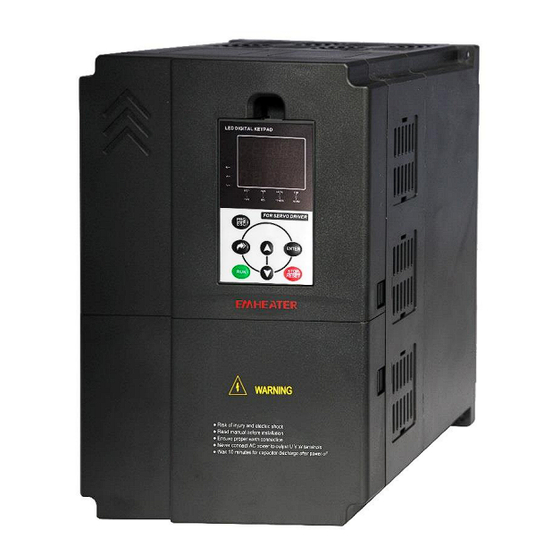
Page 9: Product Appearance And Installation Dimension
2. Product Information EM16 Series User Manual Input Current Output Current Adaptable Motor Power Capacity Model (KVA) EM16-Z3-018 36.5 18.5 EM16-Z3-022 46.5 EM16-Z3-030 EM16-Z3-037 EM16-Z3-045 EM16-Z3-055 EM16-Z3-075 EM16-Z3-090 2.4 Product appearance and installation dimension EM16 appearance and Installation Hole Dimension (mm) Diagram 2-3 Single phase 4~22KW Wall-mounted installation dimensions Appearance and installing dimension ( Unit: mm ) Matching inverter... -
Page 10: Daily Maintenance Of Servo Drives
EM16 Series User Manual 2. Product Information Appearance and installing dimension ( Unit: mm ) Matching inverter Voltege Power Range 3PH 220V 15~18.5kW Φ7 3PH 380V 30~37kW 3PH 220V 22~30kW Φ10 3PH 380V 45~55kW 3PH 220V 37~45kW Φ12 3PH 380V 75~90kW 2.5 Daily maintenance of servo drives Daily maintenance... -
Page 11: Storage Of The Servo Drive
2. Product Information EM16 Series User Manual 2. Possible reasons for the damage of filting electrolytic capacitor: poor quality of the input power supply, the environment temperature is higher, the load change frequently and the electrolyte aging. Distinguish standard: Any leakage of its liquid, if the safety valve is protruding, please test capacitor electrostatic capacitance and insulation resistance. -
Page 12: Braking Resistor Connection Description
EM16 Series User Manual 2. Product Information Recommend Recommend power of Inverter Power resistance value of Braking unit Remarks braking resistor braking resistor EM16-Z2-011 ≥ 11Ω 1500W EM16-Z2-015 ≥ 8Ω 2500W EM16-Z2-018 ≥ 8Ω 3.7 kW EM16-Z2-022 ≥ 8Ω 4.5 kW EM16-Z2-030 ≥... -
Page 13: Installation Of Servo Drive
3. Installation of Servo Drive EM16 Series User Manual 3. Installation of Servo Drive 3.1 Installation environment 1. The place with indoor vents or ventilation devices. 2. The environment temperature shall be -10℃~40℃. If the temperature is over 40℃but less than 50℃, better to take down the cover of servo drive or open the front door of cabinet to facilitate heat dissipation. -
Page 14: Peripheral Devices Connection Diagram
EM16 Series User Manual 3. Installation of Servo Drive 3.3 Peripheral Devices Connection Diagram Diagram 3-2 Peripheral Devices Connection 3.4 Model Selection of Main Circuit Peripheral Devices Table 3-1 Model Selection Diagram of Main Circuit Peripheral Devices (Recommended) Cable of Input Side Cable of Output Cable of Control MCCB... -
Page 15: Sketch And Description Of Main Circuit Terminals
3. Installation of Servo Drive EM16 Series User Manual Cable of Input Side Cable of Output Cable of Control MCCB Contactor Main Circuit Side Main Circuit Circuit Model EM16-Z2-5d5 EM16-Z2-7d5 EM16-Z2-011 EM16-Z2-015 EM16-Z2-018 EM16-Z2-022 EM16-Z2-030 EM16-Z2-037 EM16-Z2-045 Three-phase 380V EM16-Z3-7d5 EM16-Z3-011 EM16-Z3-015 EM16-Z3-018... -
Page 16: Control Circuit And Main Circuit Terminals Description
EM16 Series User Manual 3. Installation of Servo Drive Terminal symbol Function description R、S、T Three-phase AC power input terminals P+、PB Braking resistor connection External DC reactor connecting terminals-shorted by bronze before P、P+ delivery Grounding terminal or E/PE U,V,W Three-phase AC power output terminals 3.6 Control Circuit and Main Circuit Terminals Description Control Circuit and Main Circuit Wiring 3.6.1... - Page 17 3. Installation of Servo Drive EM16 Series User Manual Terminal Type Terminal Name Terminal function description Symbol Supply Generally, it provides power supply to external potentiometer with resistance range of 1 kΩ~5kΩ Supplied externally with 13V± 10% power supply, maximum output Pressure sensor +13V-GND current: 10mA...
-
Page 18: Description Of The Function Of The Pg Card Terminals Of The Servo Drive
EM16 Series User Manual 3. Installation of Servo Drive Terminal Type Terminal Name Terminal function description Symbol Voltage or Current output, voltage output by default. AO2 output type selection. Voltage or Current output, voltage output by default. Internal power supply drives DI1 to DI5 input terminals; external power supply needs to be shorted to OFF 3.6.3 Description of the function of the PG card terminals of the servo drive Terminal... -
Page 19: Operation And Display
4. Operation and Display EM16 Series User Manual 4. Operation and Display 4.1 Instruction of operation and display The operation panel can modify the function parameters of the servo drive, monitor the working status of the servo drive and control the operation of the servo drive (start, stop), etc. Its appearance and functions are shown in the figure below: Diagram 4-1 Operating Keypad Name Function... -
Page 20: Viewing And Modifying Function Codes
EM16 Series User Manual 4. Operation and Display 4.2 Viewing and Modifying Function Codes The operation panel of the EM16 adopts three-level menu. The three-level menu consists of function code group (Level I), function code (Level II), and function code setting value (level III), as shown in the following figure. - Page 21 4. Operation and Display EM16 Series User Manual Code Parameter Name Functional description Default 0: Main frequency source X Frequency source selection P0-07 1: X and Y calculation Preset frequency 0.00Hz~maximum frequency(P0-10) P0-08 50.00Hz 0: Same direction Rotating direction P0-09 1: Reverse direction Maximum frequency P0-10...
- Page 22 EM16 Series User Manual 4. Operation and Display 2: Dynamic auto-tuning without load, reverse high speed rotation 3: Static auto-tuning with load 4: Fast dynamic auto-tuning without load, reverse high speed rotation. 5: Dynamic auto-tuning without load, forward high speed rotation 6: Fast dynamic auto-tuning without load, forward high speed rotation.
- Page 23 4. Operation and Display EM16 Series User Manual Code Parameter Name Functional description Default 48: Servo pump PID selection terminal 1 49: Servo pump PID selection terminal 2 P4-03 DI4 function selection 50: CAN communication enabled 51: Slave pump terminal enabled 52: Switchover from pressure mode to speed mode 53: Slave pump address selection terminal 1 54: Slave pump address selection terminal 2...
- Page 24 EM16 Series User Manual 4. Operation and Display Code Parameter Name Functional description Default 7: Servo drive overload pre-warning 19: Undervoltage status output Relay (TA2-TC2) function P5-02 20: Communication setting selection 23: Double-discharge plunger pump sloping switchover (NO) 24: Hydraulic control NC output 25: Slave pump alarm DO1 function selection P5-03...
- Page 25 4. Operation and Display EM16 Series User Manual Code Parameter Name Functional description Default Motor overload protection 0: Disabled P9-00 selection 1: Enabled P9-01 Motor overload protection gain 0.20~10.00 1.00 P9-04 Braking voltage threshold 120%~150%(100% corresponding to 530V) 130% 0: Disabled P9-12 Input phase loss protection 1: Enabled...
- Page 26 EM16 Series User Manual 4. Operation and Display Code Parameter Name Functional description Default Output terminal state upon fault - - P9-25 Fault type - - P9-26 Group PA: Business Timing Function Code Parameter Name Functional description Default PA-00 1st runtime protection password 0~65535 PA-01 1st timed running time...
- Page 27 4. Operation and Display EM16 Series User Manual Code Parameter Name Functional description Default H1-02 Encoder installation angle 0.0°~359.9° 0.0° 0: Same H1-03 Inversion of feedback speed 1: Different H1-04 Number of pole pairs of resolver 1~50 Resolver signal fault detection 0.000: Detection invalid H1-05 2.000s...
- Page 28 EM16 Series User Manual 4. Operation and Display Code Parameter Name Functional description Default 1: Enabled H3-21 Fault detection time of 0.000s: Detection invalid 0.500s hydraulic pressure sensor 0.001s~60.000s H3-22 Setting of maximum rotational 0.0%~100.0% 10.0% speed in pressure control H3-23 Setting of minimum hydraulic 0.0%~100.0%...
- Page 29 4. Operation and Display EM16 Series User Manual Code Parameter Name Functional description Default Deceleration time from slave H3-46 0.001~5.000s 0.200s pump no speed command stop H3-47 Start valve unloading delay 0.001~5.000s 0.100s H3-48 Exit valve unloading delay 0.001~5.000s 0.100s Start valve unloading differential 0.0~H3-02(System hydraulic pressure)...
- Page 30 EM16 Series User Manual 4. Operation and Display Code Parameter Name Functional description Default Hydraulic PID algorithm H4-26 selection 1st hydraulic pressure impact 0~100.0% (Bigger than this value enters overshoot H4-29 overshoot suppression pressure 70.0% suppression) judgement thresholds 1st hydraulic pressure impact 0~1.00 (Enhanced suppression by increasing parameter H4-30 overshoot suppression...
-
Page 31: Faults And Solutions
4. Operation and Display EM16 Series User Manual Code Parameter Name Functional description Default U1-13 CAN communication 0~128 (128: Disconnection) - interference status U1-14 Number of CAN messages sent 0~65535 - U1-15 Number of CAN messages 0~65535 - received U1-16 CAN buffer use ratio 0~1.00% -... - Page 32 EM16 Series User Manual 4. Operation and Display Fault Type Possible Causes Solutions Display 5: The servo drive model is of too small 5: Select an Servo drive of higher power power class. class. 1: The input voltage is too high. 1: Adjust the voltage to normal range.
- Page 33 4. Operation and Display EM16 Series User Manual Fault Type Possible Causes Solutions Display overheat 3: The fan is damaged. 3: Replace the damaged fan. 4: The thermally sensitive resistor of the 4: Replace the damaged thermally sensitive IGBT module is damaged. resistor.
- Page 34 EM16 Series User Manual 4. Operation and Display Fault Type Possible Causes Solutions Display communicati parameters are set correctly (H2-00, H2- 2. Strengthen the CAN communication cable on fault 3. Correct the wrong wiring 2. Check if the CAN communication line contact is good CAN+/CAN- connection...
-
Page 35: Common Faults And Solutions
4. Operation and Display EM16 Series User Manual Fault Type Possible Causes Solutions Display Reverse run Err63 time reached 4.5 Common Faults and Solutions The following fault situations may be encountered during the use of the servo drive, please refer to the following methods for simple fault analysis: Failure phenomena Reason... - Page 36 EM16 Series User Manual 4. Operation and Display Failure phenomena Reason Solution power-on or running. loose. 2: Check whether the contactor is faulty. 3: Check whether 24 V power supply of the contactor is faulty. 4: Ask for technical support.
-
Page 37: Appendix I Multi-Pump Model For Injection Moulding Machines
Appendix I Multi-pump Model EM16 Series User Manual Appendix I Multi-pump model for injection moulding machines 1. Servo oil pump and pump control solution The multi-pump control is divided into two options: "multi-pump combining flow" and "multi-pump splitting flow". Multi-pump combining flow: One set of servo drives is used as the master drive, the remaining servo drives work in parallel as slave drives and the system computer outputs a set of flow and pressure analog signals. - Page 38 EM16 Series User Manual Appendix I Multi-pump Model Diagram I-2 Multi-pump splitting flow structure diagram Note: For detailed wiring and CAN communication wiring, please refer to the "Wiring", and for function code adjustment, please refer to the "Function code setting". The same motor speed can be guaranteed by communication.
- Page 39 Appendix I Multi-pump Model EM16 Series User Manual Note: One-way valve leakage is larger and at the same time from the pump's internal leakage is smaller, it will cause the pressure control state from the pump oil circuit appear unexplained high pressure phenomenon, in order to release the high pressure state of this oil section, the following ways can be taken.
- Page 40 EM16 Series User Manual Appendix I Multi-pump Model 2000rpm/min, maximum speed is 2000rpm/min for slave pump. Condition 2: When holding pressure, only the main pump is engaged and the slave pumps are completely stopped. Condition 3: To ensure the linearity of the flow, the main pump is 100rpm or more and the same speed for the slave and master pumps.
- Page 41 Appendix I Multi-pump Model EM16 Series User Manual H2-04 CAN slave address 1 Through input terminals 53 and 54, 4 H2-05 CAN slave address 2 kinds of combined splitting flow and H2-06 CAN slave address 3 combining flow control of slave pumps can be realized.
- Page 42 EM16 Series User Manual Appendix I Multi-pump Model The following shows the slave drive function code settings. Other function codes are set according to the general method for servo oil pumps. Code Parameter Name Default Description H2-01 CAN local address >...
- Page 43 Appendix I Multi-pump Model EM16 Series User Manual Diagram I-8 2+1 combined splitting flow control 1# main pump work with 2# slave pump, 3# pump switch to main pump works. Switching of 3# slave pump as main pump is achieved by disconnecting the 50# DI terminal of 3# slave pump. Other situations are analogized in turn.
- Page 44 EM16 Series User Manual Appendix I Multi-pump Model Diagram I-9 4 pump combining flow control Wiring instructions: In the case of combining flow only, the wiring is very simple, just need to connect all CAN and run enable DI terminal wires, etc.
- Page 45 Appendix I Multi-pump Model EM16 Series User Manual Diagram I-11 2+2 combined splitting flow control Wiring instructions: The upper computer provides a splitting flow signal to the drive 53# DI terminal of the main pump, the main pump uses this 53# DI signal to identify the slave pump address, while the slave pump uses this 53# DI signal to switch to the main pump and identify the slave pump address.
- Page 46 EM16 Series User Manual Appendix I Multi-pump Model Diagram I-14 3+13+1 combined splitting flow control Wiring instructions: The upper computer provides a splitting flow signal to the drive 54# DI terminal of the main pump, the main pump uses this 54# DI signal to identify the slave pump address, while the slave pump uses this 54# DI signal to switch to the main pump and identify the slave pump address.
- Page 47 Appendix I Multi-pump Model EM16 Series User Manual conflict failed. 2. Exclude the connection error 2. Check if the CAN communication line 3. Replace the control board is wrong 3. Control board failure...
-
Page 48: Appendix Ii Debugging Instructions For Single Pumps
EM16 Series User Manual Appendix II Debugging Appendix II Debugging instructions for single pumps 1. System schematic diagram Oil cylinder Injection molding Oil tank machine computer Pressure meter Pressure sensor Pressure signal Flow sensor shielded wire 0.75mm Permanent Magnet Synchronous Motor pump Manual relief valve shielded wire 0.75mm... - Page 49 Appendix II Debugging EM16 Series User Manual 3. Wiring instructions Description of the Terminal Terminal Name corresponding Note Symbol external equipment +13V Pressure sensor power supply Pressure sensor Sensor feedback 0-10V Pressure feedback feedback 0-10V Pressure given Pressure given Syestem given AI common 0-10V Flow given Flow given...
- Page 50 EM16 Series User Manual Appendix II Debugging Auto correction: H3-20=1, press “RUN” to zero drift auto correction, and after zero drift auto correction is completed, The value of the HI zero drift auto correction parameter H3-20 will automatically revert to "0". Manual correction: When the drive is not enabled, the value of U1-04 (Corresponding to AI1), U1-05(Corresponding to AI2), U0-06(Corresponding to AI3), please write the maximum values of the 3 parameters viewed plus 10mV into the function codes P4-18, P4-23 and P4-28 respectively.
- Page 51 Appendix II Debugging EM16 Series User Manual Code Parameter Name Functional description Note speed unloading Due to the internal leakage of the oil pump, when the system is H3-09 Minimum flow Factory default is 0.5% not given pressure and flow commands, the hydraulic oil in the oil circuit can flow backwards into the tank causing...
Need help?
Do you have a question about the EM16-Z and is the answer not in the manual?
Questions and answers