
Summary of Contents for INDO CUBICA
- Page 1 MANUAL DE INSTRUCCIONES INSTRUCTIONS MANUAL UNIDAD DE REFRACCIÓN REFRACTION OPHTHALMIC UNIT...
-
Page 2: Información General
! & 8#% " " 8 + + -" 0 < " " < 0 Thank you for purchasing the CUBICA unit Gracias por adquirir la Unidad CUBICA GENERAL INFORMATION INFORMACIÓN GENERAL This user’s manual includes basic information Este Manual Instrucciones contiene about the unit, the assembly procedure, its información de la unidad, montaje, configuración y... - Page 3 WARNINGS: ADVERTENCIAS: -To assure the correct usage of the product and to -Para garantizar el uso correcto del producto y prevent risks to the operator and third parts or prevenir riesgos al operador y terceras partes o damages to the property, warnings and alarms are daños a la propiedad, se han dispuesto avisos y placed on the stand and described in the user’s advertencias en el equipo y descripción de los...
- Page 4 -It is a duty of the owner to maintain and keep the unidad en perfectas condiciones de funcionamiento y unit in perfect cleaning and working conditions. limpieza. -CUBICA Unit is classified as an equipment not -La unidad CUBICA está clasificada como un equipo suitable used...
-
Page 5: Descripción De La Unidad
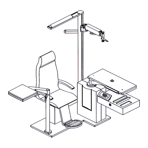
DESCRIPCIÓN DE LA UNIDAD DESCRIPTION OF THE UNIT Equipo destinado soporte instrumentos Equipment intended for the ophthalmic instrument oftalmológicos: lámpara de hendidura, oftalmómetro, support: slit lamp, ophthalmometre, retinographs, retinógrafos, etc., mediante suministro de regulación etc., providing electronically regulated power, electrónica, posicionamiento instrumentos instruments positioning and patient placement in a... -
Page 6: Descripción General
2.- DESCRIPCIÓN GENERAL 2.- GENERAL DESCRIPTION... - Page 7 3.-MONTAJE. Figura 1 3.-ASSEMBLY. Figure 1 Tras desembalar la unidad Cubica y el Sillón CH-50- After unpacking the unit and the chair CH-50-C and C y establecido el emplazamiento del equipo ha de having established the location of the equipment, you pasar el cable del sillón (5) procedente de la columna...
- Page 8 Montaje. Figura 2 Assembly. Figure 2 Fijar a la base de la unidad la placa soporte Fix to the base of the unit the connectors support conectores (1) mediante los tornillos 2 x M6 x 15 plate (1) by means of the screws 2 x M6 x 15 DIN912 DIN 912 (2) y las arandelas 2 x 12 x 1,45 (3).
- Page 9 Montaje. Figura 3 Assembly. Figure 3 Fix the column of the lamp (1) to the supports (2) by Fijar la columna de la lámpara (1) a los soportes (2) mediante las bridas (3) y los tornillos 4 x M8 x 30 means of the bridles (3) and the screws 4 x M8 x 30 DIN 912 (4) with its washers 4 x 8,4 x...
- Page 10 Assembly. Figure 4 Montaje. Figura 4 Mount the additional supports in the lamp column. Montar los soportes adicionales en la columna de la lámpara. Previamente desmontar la tapa del extremo Previously you have to dismount the cover at the end of the column (14) unscrewing the screws 3 x M6 x de la columna (14) desatornillando los tornillos 3 x M6 x 16 DIN 7991 (15).
- Page 11 Montaje. Figura 5 Assembly. Figure 5 Colocar la tapa (1) fijándola con los tornillos 3 x M6 x Place the tap (1) fixing it with the screws 3 x M6 x 16 DIN 7991 (2) at the end of the lamp column. 16 DIN 7991 (2) en el extremo de la columna de la lámpara.
- Page 12 Montaje. Figura 6 Assembly. Figure 6 Pasar el cable eléctrico (1) procedente de las Pass the electrical cable (1) from the tabletop conexiones de la sobremesa a través del eje del connections through the rotating group axis (2). grupo de giro (2). Attention! Place and fix cabling in the maximum ¡Atención! Ajustar y fijar cableado en la posición height position of the unit.
- Page 13 Assembly. Figure 7 Montaje. Figura 7 Place the chair elevation group cover (1) and fix it by Colocar el cubre del grupo de elevación del sillón (1) means of the screws 4 x M4 x 10 DIN 7991 (2). y fijarlo mediante los tornillos 4 x M4 x 10 DIN 7991 Place back chassis cover (3) and fix it by means of (2).
- Page 14 Montaje. Figura 8 Assembly. Figure 8 Once you made the electrical connectivity (to see hecha instalación eléctrica (ver procedure of electrical connections) place the back procedimiento de conexiones eléctricas) colocar el cover of the chassis (1) fixing it with the screws 6 x cubre anterior del chasis (1) fijándolo con los tornillos M6 x 90 DIN 912 (2).
- Page 15 Montaje Brazo Tercer Instrumento. Figura 9 Assembly of the Third Instrument Arm. Figure 9 (detail) (detalle) Before initiating the assembly you have to make the Antes de iniciar el montaje se han de realizar los indicated drills in the cover base detail view of the taladros indicados en la vista detalle del cubre de la unit (1).
- Page 16 Assembly of the Third Instrument Arm. Figure 9 Montaje Brazo Tercer Instrumento. Figura 9 4.-PROCEDIMIENTO DE CONEXIONADO 4.-PROCEDURE OF CONNECTION Antes realizar conexiones, Attention! Before carrying desconecte la unidad de la red. connections, disconnect the unit from the power supply. SILLÓN CHAIR •...
- Page 17 TABLETOP CABLING MANGUERA DE SOBREMESA • Potentiometer (51, 52, 53). • Potenciómetro (51, 52, 53). • Leg’s safety (1, 2). • Fixing Point (take the supply from CN2 trafo • Seguridad piernas (1,2). connector CN2 and through the aerial from the •...
- Page 18 • These two micros activate the cable we placed • Ambos micros controlan cableado que se from the strip at the lower part of the optional entrega desde regleta ubicada en parte inferior tabletop till column chassis without sobremesa y sin conectar en carta principal. Ver connecting in the main card.
- Page 19 Bandeja de Instrumentos de Mano Hand instruments tray La unidad incorpora encima del cajón de lentes unos The unit has been added over the lenses drawer a alojamientos para los instrumentos de mano y el placement for the hand instruments and the projector mando a distancia del proyector.
- Page 20 5.-SETTINGS 5.-CONFIGURACIÓN Slit Lamp Lámpara Hendidura • Be sure unit is switched off. • Asegúrese que la unidad está desconectada. • Connect the connector 9 in the maximum outlet • Conecte el conector 9 en la salida máxima al to the transformer for Slit Lamp. If the bulb of trafo para la lámpara de hendidura.
- Page 21 6.-SEGURIDADES 6.-SECURITIES Para garantizar una total seguridad, el equipo se ha In order to use with a complete safety, the dotado de los siguientes elementos de protección: equipment disposes of the following protection elements: " < 0 " + " "# $ %&...
-
Page 22: Caja De Conexiones
< = CAJA DE CONEXIONES < .-CONNECTION BOX Asegúrese de usar una toma de red con Be sure to use a Power Supply with Earth toma de tierra a fin de evitar choques Connection in order to prevent electric eléctricos o fuego en caso de fugas de shock or fire in case of power failures. -
Page 23: Control Pannel
8.-FUNCIONES DEL PANEL DE MANDO 8.-CONTROL PANNEL 1. Puesta en Marcha y Paro. El led piloto indica si 1. General Switch ON/OFF. The led light indicates la función está activada o no. Si la unidad está if the function is activated or no. If the unit is en marcha, al pulsar la tecla, se para, switch on, when pressing the key, it stops, desactivando... - Page 24 9.-TRAY OPERATING MODE 9.-FUNCIONAMIENTO DE LA BANDEJA When placing the tabletop in the working position Al colocar el sobremesa en posición de trabajo se the rotating micro switch gets activated and then the activa el micro de giro y se conecta el primer first instrument is connected.
- Page 25 10.-REGULATION FORCE OF THE VT ARM 10.-REGULACIÓN DE LA FUERZA DEL BRAZO FORÓPTERO To change the regulation force do as follow: 1. Slacke the safety screw (b). Para modificar la regulación de la fuerza haga 2. With an Allen tool turn the screw (a) to get lo siguiente: more or less force F.
-
Page 26: Mantenimiento
11.-MANTENIMIENTO 11.-MAINTENANCE • La superficie de la sobremesa puede limpiarse • The surface of tabletop can be cleaned by a con una pieza de algodón humedecido con agua piece of cotton dampened with water and neuter y detergente neutro. Secar inmediatamente. detergent. - Page 27 Substitución Lámpara Halógena (100 w) Replacement of the Halogen Bulb (100 w) 1. Extraer el cristal protector insertando un 1. With the help of a thin screwdriver leving destornillador y efectuar palanca entre la between the metallic support of the protector pestaña metálica del protector y la parte and the metallic part of the lamp-holder, remove metálica del portalámparas.
- Page 28 12.-INFORMACIÓN TÉCNICA. MARCAS / TECHNICAL INFORMATION. MARKS Unidad / Unit CUBICA: Concepto Concepts 110 V 230 V Potencia Total Power 110V/60Hz 230V/50Hz Consumption Max Consumo Máximo 1000 W 1300 W Clasificación Eléctrica Electrical Classification Class I, B Grado de Protección Eléctrico...
- Page 30 <@= 5=00 <@= )#A '. '#, -* ") >*B >. C , "'" $ , . )#? , D' 0 @ ( * *, * , *( ) 6 ( : 106 ;%6 ( )" ! !& )" % $ # ! # #F( !"...
- Page 31 15.-DIAGRAMA ELÉCTRICO / ELECTRIC DIAGRAM...
Need help?
Do you have a question about the CUBICA and is the answer not in the manual?
Questions and answers