Advertisement
Quick Links
+
LSPM 1.0
LUMILOOP GmbH
May 28, 2024
The most recent version of this document and the full
(+)
length LSPM
User's Manual can be found at
lumiloop.de.
1
System Overview
+
+
The LSPM 1.0
/2.0
system consists of a single board
computer with an integrated high-speed RF power
meter and a touchscreen display, a power cord and
a USB ýash drive.
+
+
The LSPM 1.0
/2.0
installed LUMILOOP TCP Server, LUMILOOP GUI,
manufacturer calibration data and optionally accred-
ited calibration data.
The USB ýash drive contains the LUMILOOP Win-
dows Installer, including the LUMILOOP GUI for
remote "+"device access, as well as a copy of the
calibration data.
Third party EMC software communicates with
+
+
LSPM 1.0
/2.0
using SCPI commands exchanged
over TCP/IP.
2
System Startup
1. Connect the included mains power cord to the
+
LSPM
.
2. Switch on the LSPM 1.0
front panel switch to "green" and observe the
+
/2.0
Quick Start
Guide
device is delivered with a pre-
+
+
/2.0
by setting the
green "Power" LED next to the RF connectors
starting to ýash. The LUMILOOP TCP Server
and the LUMILOOP "+"Device GUI will start au-
tomatically. The green "Power" LED will light up
constantly to show correct operation.
3. The system will be cooled down or heated to
its operating temperature. This is indicated by
the red "Temperature" LED. Additionally, the
"+"Device GUI will show the message <Settling
Temperature. Please wait.=. After reaching the
required operating temperature, the red "Tem-
perature" LED will turn oû and the notiücation
www.
will disappear.
4. Additional LUMILOOP LSProbe and/or LSPM
devices can be connected to the LSPM
USB.
3
LUMILOOP "+"Device GUI
The LUMILOOP "+"Device GUI is started automati-
cally after system boot, communicating with the LU-
MILOOP TCP Server running in the background.
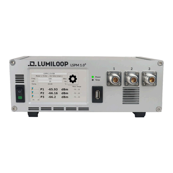
1. The GUI indicates proper operation after reach-
ing the operating temperature by displaying RF
power values.
2. As shown below, the RF power values of all
available channels are displayed by the GUI.
The maximum and minimum calibrated power
value for the set mode and frequency are dis-
played at the right edge of the screen.
+
via
Advertisement

Related Manuals for Lumiloop LSPM 1.0+


Summary of Contents for Lumiloop LSPM 1.0+
- Page 1 "Power" LED next to the RF connectors starting to ýash. The LUMILOOP TCP Server and the LUMILOOP "+"Device GUI will start au- tomatically. The green "Power" LED will light up LSPM 1.0 /2.0 Quick Start constantly to show correct operation.
- Page 2 Register your LUMILOOP device and get a free one year warranty extension! 4. To use the LUMILOOP GUI from a remote com- Applicable to all devices, which are currently puter, install the LUMILOOP Windows Installer...
Need help?
Do you have a question about the LSPM 1.0+ and is the answer not in the manual?
Questions and answers