
Summary of Contents for technotrans omega.k 340
- Page 1 Instruction Manual ORIGINAL INSTRUCTION MANUAL omega.k/.t 340, 420, 500 L (cc) 90000374263-03 - EN 2022-1107...
- Page 2 The main components, devices, arrangements, software as well as the control and instrumentation equipment on all of our products are protected both at home and abroad by patent applications, patents, utility models or copyrights. Copyright by technotrans SE Robert-Linnemann-Straße 17 D-48336 Sassenberg Federal Republic of Germany technotrans SE...
-
Page 3: Table Of Contents
Contact Addresses..........................6 Manufacturer's address ........................6 Service addresses ..........................6 Making contact........................... 8 About this manual ..........................9 Use and storage ..........................9 Target audience ..........................10 Explanation of the various notes ..................... 11 Seal of quality ..........................12 Further applicable documents ......................12 Liability and warranty ..........................13 General information ......................... - Page 4 Transport...............................38 Transport and packaging material ....................38 Transport to the installation location ....................39 7.2.1 General information ........................39 7.2.2 Use of cranes..........................40 Installation site ..........................41 Setting Up..............................42 Notes..............................42 Installation............................43 Installation of pipes .......................... 44 Connections ............................. 46 Electrical connection........................
- Page 5 Troubleshooting ...........................80 11.1 Notes..............................80 11.2 General malfunctions........................81 11.3 Electrical connection........................82 11.4 Cooling circuit / Temperature control circuit ..................83 11.5 Refrigerant circuit..........................85 11.6 Control unit............................86 11.6.1 Fault messages........................86 Disconnecting the device ........................92 12.1 Notes..............................92 12.2 Dismantling ............................
-
Page 6: Contact Addresses
48336 Sassenberg Phone +49 (0) 25 83-301-1000 +49 (0) 25 83-301-1030 Germany Service addresses Europe technotrans SE technotrans graphics ltd. Robert-Linnemann-Straße 17 Axis One, Brunel Way 48336 Sassenberg Severalls Business Park Phone: +49 (0) 25 83-301-2000 Colchester, Essex CO4 9QX... - Page 7 Contact Addresses Asia technotrans Asia-Pacific limited, Japan branch technotrans technologies pte.ltd 322 Sannomiya Venture Building 66 Kallang Pudding Road #04-03 4-1-23 Hamabe-Dori, Chuo-Ku Hor Kew Business Centre Kobe 651-0083 Singapore 329324 Phone: +81 3 5484 3180 Phone: +65 6508 6800...
-
Page 8: Making Contact
Contact Addresses Making contact Please keep the following details ready (see the type plate of the unit) when contacting us (e.g. for spare part orders, warranty claims, etc.): • Product name • Serial no. NOTE If necessary, enter the information, which is stated on the type plate of the unit, into the table. -
Page 9: About This Manual
About this manual About this manual Use and storage NOTE Prior to performing any work on the unit/system, read the instruction manual. The following points must be noted: • The instruction manual is an integral part of the unit/system and must be available to the operating personnel at the unit/system at all times. -
Page 10: Target Audience
About this manual Target audience When working with the unit/system, the various tasks must be assigned to specific groups of persons. Depending on the location of use, the necessary qualification of the personnel may be subject to varying statutory provisions. The operator must ensure compliance with the relevant laws. -
Page 11: Explanation Of The Various Notes
About this manual Explanation of the various notes The warning notes are preceded by signal words indicating the severity of the hazard. Compliance with the warning notes is imperative in order to avoid accidents, injuries and damage to property. Explanation of warning notices used in this manual: DANGER Short description of danger The signal word DANGER identifies an immediately threatening danger. -
Page 12: Seal Of Quality
About this manual Seal of quality The seal of quality "gdsCert" of gds GmbH (service provider for technical documentation) is a proof of quality for technical documentation. With the "gdsCert" seal of quality, the manufacturer provides proof of the high standard of the technical documentation and of the compliance with the relevant standards and guidelines. -
Page 13: Liability And Warranty
Liability and warranty Liability and warranty General information The unit/system has been manufactured in line with the state of the art as well as the recognised safety regulations and standards. Still, its use may jeopardise the health and safety of the user or third parties or cause damage to the unit/system or other property. -
Page 14: Terms Of Warranty
Liability and warranty Terms of warranty Warranty claims are limited to the contractual partner of the technotrans system. Unless otherwise agreed, the warranty period concerning quality defects is twelve months from the date of shipment from the factory. The warranty covers all of the material and labour costs for a repair at the factory. - Page 15 Liability and warranty NOTE Removing type plates will make the warranty claim expire. 10437-02 Fig. 1: Sealings Sealings may exist at various different locations at the unit or plant: Sealing wax (Application example) Seals (Application example) Seal stickers (Application example) NOTE The warranty will be rendered void if sealings are broken without authorisation.
-
Page 16: Information On It Safety
SE and its subsidiaries shall not be held liable for any damage and/or loss caused by such security breaches, unauthorised access, faults, intrusion or... -
Page 17: Safety
Safety Safety General information NOTE Every person who is ordered to work on the unit/system must have read and understood these instructions and, in particular, the "Safety" chapter. If necessary, in-house instruction should be provided, taking into account the technical qualifications of the personnel concerned. The "Safety"... -
Page 18: Intended Use
Safety Intended use The unit or the system is intended solely for the application outlined in the “Description/Overview” section and only with the components supplied and approved. Using the unit for purposes other than those mentioned above is considered contrary to the intended use. The manufacturer cannot be held liable for any damage resulting from such use. - Page 19 Safety There is an increased risk of injury if the safety devices and guards are disabled. Never dismantle or disable any safety devices or guards. • Check the safety devices and guards daily for correct operation. • Report any faults and defects concerning the safety devices and guards to the customer service without delay.
-
Page 20: Transport And Installation/Start-Up
Safety Transport and installation/start-up There is an increased risk of injury for persons who perform tasks for which they are neither qualified nor trained. Only persons who are familiar with the tasks, who have been informed about the associated hazards have the necessary qualifications are authorised to transport the unit. -
Page 21: Operation
Safety Operation • Operation is permissible only if all of the components are in a perfect technical state and proper operational condition and if they are used in line with the intended purpose. • Avoid any operation that compromises the safety of the unit/system. •... -
Page 22: Residual Risks
Safety Residual risks Any unavoidable, design-based residual risks (if present) are mentioned and described in this instruction manual in the corresponding sections. Use of chemicals Health hazard! The use of chemicals can present a health hazard. • When handling chemicals, always wear protective gloves, eyewear, and clothing. -
Page 23: Use Of Cleaning Agents
Safety 4.10 Use of cleaning agents No material, i.e. neither metals nor plastics, can be certified to be completely chemically resistant. Due to the large number of available additives and cleaning agents, the recipes of which are subject to change, the manufacturer cannot assume any liability for damage attributable to the influence of such substances. -
Page 24: Safety Labels
Safety 4.11 Safety labels Notes and symbols on the equipment/system, e.g. safety labels and plates, must be absolutely complied with. Do not remove them and ensure that they are fully legible. NOTE Destroyed or illegible marks/symbols must be replaced immediately. Warning –... -
Page 25: Description / Overview
Description / Overview Description / Overview General information Unit for temperature control of process media at external parts and components. The temperature control unit consists of the following main functional groups: • Cooling/Temperature-control circuit with integrated pump for conveying process medium. omega.k - without integrated heater. -
Page 26: Factory Protective Measures
Description / Overview Factory protective measures • Outer painting/coating/anodisation against corrosion. • Protective earthing / potential equalization for static discharge. • Warning labels (in accordance with the German regulation BGV A8) e.g.“Warning – hot surface” and “Warning – dangerous voltage”. ogle Foreseeable misuse The following points describe a foreseeable misuse of the unit/system:... -
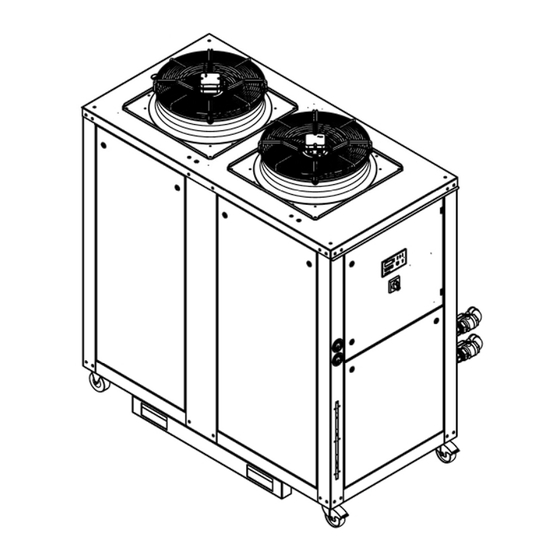
Page 27: System Layout
System Layout System Layout General view 14217 Fig. 2: omega Device control unit 2 Maintenance switch 3 Control cabinet 4 Connection points 5 Cooling/temperature-control circuit Refrigeration circuit NOTE Electrical components are marked with reference designators. See also the circuit diagram. -
Page 28: Overview
System Layout Overview 6.2.1 Refrigerant circuit The following components are included in the unit (example). Component Description Compressor Condenser Air filter mat (at rear or side panel of device, depending on device version) High-pressure switch with reset button Low-pressure switch High-pressure sensor... - Page 29 System Layout Component Description Expansion valve Filter dryer Refrigerant solenoid valve Refrigerant collector Refrigerant sight glass Heat exchanger Service connection...
-
Page 30: Cooling Circuit / Temperature Control Circuit
System Layout 6.2.2 Cooling circuit / Temperature control circuit The following components are included in the unit (example). Component Description Flow monitor Automatic vent valve Pressure gauge The temperature sensor is located in the pipe fitting (see the arrow). Pump Buffer tank Low-water level switch Safety valve... - Page 31 System Layout Component Description Heater with safety temperature limiter and reset button (see arrow) Expansion vessel Overflow valve Filter housing with filter Fill and drain valve Shut-off/drain valve...
-
Page 32: Schematic System Diagram
System Layout Schematic system diagram Fig. 3: Schematic system diagram... - Page 33 System Layout Refrigeration circuit Cooling/temperature control circuit Flow monitor *) 1x omega 60 - 250 Low water level switch 2x omega 340 - 500 Safety valve Condenser Expansion vessel Air filter mat Buffer tank Refrigerant collector 25 Pump Filter dryer Manual venting vavle*) Refrigerant sight glass Heater *)
-
Page 34: Connections
System Layout Connections 12706-02 Rear view Side view Front view Fig. 4: omega.k/.t Power supply connector Drain connector (open system) Inlet for connection cables in the unit Filling for cooling / temperature control circuit (open system) Temperature control water inlet (return flow) Filling for cooling / temperature control circuit (closed system) Temperature control water outlet (feed flow) -
Page 35: Refrigeration Unit
System Layout Refrigeration unit 6.5.1 General information If refrigeration units are used, please comply with the rules and regulations that are in force in the country where the system is set up. Information concerning the refrigerant and the filling quantities can be found in the “Technical Data”... -
Page 36: Obligation To Maintain Records
System Layout 6.5.2 Obligation to maintain records annual leak test semi-annual leak test Refrigeration unit hermetically sealed Refrigeration units Refrigerant refrigeration unit R134a, as of a CO equivalent (global warming potential) of R407C, 5,0 t 10,0 t 50,0 t R410A, R513A In accordance with the F-gases regulation (EU regulation 517/2014), the operators must maintain records about systems that are subject to statutory leak tests. -
Page 37: Overflow Valve
System Layout Overflow valve 13520 Fig. 5: Overflow valve (example) Use and Allen key (1) to set the pressure at the overflow valve (2). Clockwise rotation/ Pressure increase screwing-in Anti-clockwise rotation/ Pressure decrease screwing-out NOTE The overflow valve can be set during back pressure or during media flow. -
Page 38: Transport
Transport Transport The following must be observed in order to avoid injuries and damage to property: • Only qualified personnel are authorised to perform these tasks. • Comply with the information given in the "Safety" section. Transport and packaging material Check the packaging for transportation damage. -
Page 39: Transport To The Installation Location
Transport Transport to the installation location 7.2.1 General information WARNING Danger for persons! Increased risk of injuries through improper transport. The transport of the unit should be carried out only by suitably qualified persons who are familiar with the unit and who have been informed as to potential hazards. -
Page 40: Use Of Cranes
The eyebolts automatically adapt to the direction of pull. • Transverse loads are avoided. • Eyebolts can be ordered via the technotrans Service Department. If a crane is used in order to transport the equipment, there are 4 attachment points located on the frame. •... -
Page 41: Installation Site
Transport Load handling equipment: The handling equipment (webbing sling, chain, rope, etc.) must be chosen to ensure that in the comply with local and legal requirements and guarantee the safe transport. Angle of inclination: The inclination angle relative to the vertical must be ≤ 60°. <... -
Page 42: Setting Up
Setting Up Setting Up Notes The following must be observed in order to avoid injuries and damage to property: • Only qualified personnel are authorised to perform these tasks. • Comply with the information given in the "Safety" section. WARNING Risk due to incorrect installation/start-up! There is an increased risk of injury for persons who perform tasks for which they are neither qualified nor trained. -
Page 43: Installation
Setting Up Installation NOTICE Damage to device at ambient temperatures ≤ 4.0 °C (39.2 °F)! Risk of damage to the device through freezing. The device must remain in an operationally ready state at temperatures ≤ 4°C (39.2°F). The power supply must not be interrupted and the enabling contact must be closed. -
Page 44: Installation Of Pipes
Setting Up Installation of pipes NOTICE Damage through dirt particles! Dirt particles in customer-provided installations (e.g. pipes, hoses, ...) may lead to malfunctions or damage to the components or unit/system. • Ensure that the customer-provided installations (e.g. pipes, hoses, ...) are free from dirt particles. - Page 45 Setting Up • In order to avoid vibrations, there must be a sufficient number of fastening points. • Suitable hose connectors for the flexible connection of the various devices are to be used. • Suitable shut-off devices, such as ball valves, are to be used. •...
-
Page 46: Connections
Setting Up Connections NOTICE Risk of damage to the components! When torquing/re-tightening connections, fasteners and joints, this may cause damage or leaks. Always use a proper tool to hold the counterpart in place. Carry out connection to unit via flexible, pressure-resistant hoses. NOTE Connection sizes according to the "Technical Data"... -
Page 47: Electrical Connection
Setting Up Electrical connection 8.5.1 General information DANGER Danger to life due to electrical hazard! There is a risk of death by electric shock if the connected voltages are not correct. • Only qualified and specialised personnel is authorised to perform the connection. -
Page 48: External Signals
Setting Up NOTICE Impairment of the unit operation! EMC disturbance may affect the unit function negatively and/or damage components in case of insufficient equipotential bonding. • If devices/machines are electrically coupled, additional local equipotential bonding must be provided between the devices/machines. •... -
Page 49: Residual-Current-Operated Circuit-Breaker
Setting Up 8.5.3 Residual-current-operated circuit-breaker The manufacturer recommends using residual current devices (RCDs), if the chiller is to be powered via the customer’s network (in-house network). Other devices (consumers, power sockets, ...) may not be set up behind the residual current device. -
Page 50: Glycerine-Filled Pressure Gauge
Setting Up Glycerine-filled pressure gauge 11478-01 Variant 1 Variant 2 Fig. 9: Glycerine-filled pressure gauge Depending on the variant, glycerine-filled pressure gauges (2) are equipped with a protective cap (1) or rubber membrane (3) for transport in order to prevent the glycerine from leaking. -
Page 51: Filling
Setting Up Filling WARNING Health hazard! The use of chemicals can present a health hazard. • When handling chemicals, always wear protective gloves, eyewear, and clothing. • Observe the safety data sheets. NOTICE Damage to components! Damage to the pump due to dry operation. Never start the unit when it is not, or only insufficiently, filled. -
Page 52: Antifreeze And Anticorrosion Agents
Frost damage may be the result of one of the following factors: • Dirt in the cooling/temperature control circuit • pump fault • Air pockets in the system (applies only to units with closed systems). Part no. (technotrans) Description 078403230 Clariant Antifrogen N 078403235 BP C 2230 NOTICE... - Page 53 Setting Up NOTE • Refer to the specification of the manufacturer! • See the "Technical data" section. • The anti-freezing agent concentration must be adapted to the conditions on site (climate zone, ambient temperature). Frost resistance of Antifrogen N/water mixtures of different concentrations (example): minimum maximum...
-
Page 54: Filling The Cooling/Temperature Control Circuit
Setting Up 8.7.2 Filling the cooling/temperature control circuit For the initial start-up, fill the cooling/temperature control circuit with a water/glycol mixture in accordance with the information in the chapter "Anti-freeze and anti- corrosion protection". Perform the following steps for filling: Open the shut-off valves of the temperature control water inlet/outlet (if included). -
Page 55: Venting Of Closed Circuits
Setting Up Venting of closed circuits In order to ensure the correct operation and operational safety of closed circuits, vent the entire system thoroughly at start-up. NOTICE Damage to components! Insufficient venting may damage the unit. If venting at the highest point is not possible, there is a risk that some residual air remains entrapped in the system. -
Page 56: Operation
Operation Operation Notes The following must be observed in order to avoid injuries and damage to property: • Only qualified personnel are authorised to perform these tasks. • Comply with the information given in the "Safety" section. WARNING Risk of injury due to automatic restart! For example, during a power failure fans or speed-controlled motors can switch on or off automatically. -
Page 57: Adjustments
Operation Adjustments Unit • Check the shut-off valves and open them, if necessary (feed flow and return flow). Cooling medium tank • Check the filling level. Top it up, if necessary. Switching the unit on: Use the maintenance switch to turn on the device. NOTE Check the direction of rotation of the pump(s) only during the initial commissioning of the system. - Page 58 Operation Cooling circuit: Check the desired parameters (e.g. the set temperature) via the control unit. Adjust them if necessary. Refer to the "Control unit" chapter. Switching the unit off: Switch the unit off via the maintenance switch.
-
Page 59: Control Unit
Control unit NOTICE Damage to the unit! The unit function cannot be ensured if the system configuration is tampered with. The values set at delivery are basic settings and may only be changed after consulting technotrans. 9.3.1 TEC 301 °C/°F Info... -
Page 60: Actual Value Display
Operation 9.3.2 Actual value display Use the UP and DOWN button to select the applicable LED (°C/°F, Info, bar/psi). Depending on the selected LED (e.g., temperature, pressure) the actual value is indicated on the display. Please refer also to the following chapters. 9.3.3 Setpoint adjustment Select the corresponding LED by way of the up and down key. -
Page 61: Led Display
Operation 9.3.4 LED Display LED on LED flashes LED off Display Description LED off: The unit is not in operation. The external request signal is not active. LED on: The unit is in operation. The external "enable" signal is activated. The LED illuminates when a warning is pending. - Page 62 Operation Display Description °C/°F Indication of the current temperature in the feed flow of the cooling/temperature control circuit. Flashing display: The temperature is out of the set temperature range. See the chapter "A parameters", parameters A4, A5. °C/°F + When the SET key is pressed: Adjustment of the set temperature in the feed flow of the cooling/temperature control circuit.
- Page 63 Operation Display Description °C/°F + Mode of operation: "No cooling" *) Select the function as follows: • Press and hold the SET button and use the UP button to adjust the maximum set temperature. • Release the SET button. • Press the SET button again and then actuate the UP button.
-
Page 64: A-Parameters
Operation 9.3.5 A-Parameters Keep the up and down keys pressed simultaneously for approx. 5 seconds. The first parameter A0 will be displayed. Select the parameter by way of the up and down key. Press and hold the SET key. Adjust the value with the up and down key while still holding the SET key. Release the SET key. - Page 65 Operation Parameter Description Default Range value Indication of the software version. 42. -- -- Selection of the temperature and pressure unit. °C / b °C / b (bar) °F / b (bar) °C / p (psi) °F / p (psi) Indication of the software identification number.
- Page 66 Operation Parameter Description Default Range value Tripping of the compressor circuit breaker leads to a collective fault message. A17 *) Tripping of the circuit breaker or safety temperature limiter of the fan leads to a collective fault message. Tripping of the heater circuit breaker or safety temperature limiter A18 *) of the heater leads to a collective fault message.
-
Page 67: Temperature Limits
Operation 9.3.6 Temperature limits The display flashes. Fault signal contact: Permanent alarm message (only if parameter A12 = 1 or 2) Upper alarm temperature limit Fault signal contact: 0.6 seconds ON / 0.6 seconds OFF (parameter A4) (only if parameter A12 = 2) Fault signal contact: 1.0 seconds ON / 1.0 seconds OFF (only if parameter A12 = 2) Set temperature... -
Page 68: Maintenance
Maintenance 10 Maintenance 10.1 Notes The following must be observed in order to avoid injuries and damage to property: • Only qualified personnel are authorised to perform these tasks. • Comply with the information given in the "Safety" section. DANGER Risk of injury caused by electric current! When the device is open, parts of the device may be energised and cause an electric shock when they are touched. - Page 69 Maintenance Note concerning the protection of the environment The improper disposal of the media/liquids that are used has a negative impact on the environment. • Ensure that the media/liquids are not released into the sewage system or soil. • The media/liquids must be disposed of separately and supplied separately to the recycling centres.
-
Page 70: Maintenance Plan
In the case of different hours of operation, the maintenance intervals must be adapted accordingly. NOTE • The technotrans service department performs work concerning the refrigeration unit (among others) (e.g. leak checks, refrigeration checks). If required, contact the technotrans service. •... - Page 71 Green: No moisture in the refrigerant. • Yellow: Moisture in the refrigerant (contact the technotrans service department). Check the refrigerant quantity with active compressor(s). • A continuous formation of bubbles can indicate a lack of refrigerant. Contact the technotrans service department.
- Page 72 (refrigeration circuit) local rules and regulations (e.g. F-gases regulation). specialised personnel / Contact The following types of refrigeration units must be inspected the technotrans for leaks: service department • Refrigeration units with a refrigerant filling quantity of more than five tonnes (5 t) of CO equivalent.
-
Page 73: Cooling Circuit / Temperature Control Circuit
Maintenance Maintenance interval: 3 years Component Maintenance task Auxiliary devices Load contactor of Replace load contactor of compressor. compressor 10.3 Cooling circuit / Temperature control circuit Check the static system pressure: Information concerning the pressure can be found in the “Technical Data” section. -
Page 74: Filter
Maintenance 10.3.1 Filter WARNING Health hazard! The use of chemicals can present a health hazard. • When handling chemicals, always wear protective gloves, eyewear, and clothing. • Observe the safety data sheets. NOTE Filters in the cooling/temperature control circuit are optional for this unit. The manufacturer recommends the installation of a filter system in the feed line and/or return line of the cooling/temperature control circuit. -
Page 75: Antifreeze And Anticorrosion Agents
Maintenance 10.3.2 Antifreeze and anticorrosion agents To ensure sufficient concentration of the anti-freeze and corrosion protection agent, check the concentration according to the maintenance schedule. This test is carried out using a conventional density measuring system or a refractometer. Observe the manufacturer’ product information. Check/top up an anti-freezing and anti-corrosion agent as follows: Take a sample from the control circuit (e.g. -
Page 76: Expansion Vessel
Maintenance 10.3.3 Expansion vessel NOTE The system must be depressurised for checking / filling. If the system is not depressurised, system pressure of the system is measured. Checking the gas admission pressure: Unscrew the protective cap of the valve on the expansion vessel. Connect the suitable filling connection to the pressure gauge. -
Page 77: Refrigerant Circuit
• Used refrigerants must be returned to a certified company for reclamation. NOTE In case any problems arise, please contact the technotrans service department. • The technotrans service department performs work concerning the refrigeration unit (among others) (e.g. leak checks, refrigeration checks). -
Page 78: Refrigerant Sight Glass
The colour of the indicator reveals whether or not the refrigerant contains moisture. • Green: No moisture in the refrigerant. • Yellow: Moisture in the refrigerant (contact the technotrans service department). Features indicating malfunctions: • Change of indicator colour from green to yellow (indicating moisture in the refrigeration circuit). -
Page 79: Changing The Filter Mat
Maintenance 10.4.2 Changing the filter mat 14232 Fig. 15: Changing the filter mat (example) Maintenance switch Knurled screw Filter mat Holder Switch the unit off via the maintenance switch (1). Loosen the knurled screw (3) and turn bracket (4) to the side. Remove filter mat (2) and clean or replace if necessary. -
Page 80: Troubleshooting
Troubleshooting 11 Troubleshooting 11.1 Notes The following must be observed in order to avoid injuries and damage to property: • Only qualified personnel are authorised to perform these tasks. • Comply with the information given in the "Safety" section. DANGER Risk of injury caused by electric current! When the device is open, parts of the device may be energised and cause an electric shock when they are touched. -
Page 81: General Malfunctions
Troubleshooting WARNING Danger to persons due to heavy objects! When installing or removing components of the system (e.g., pumps, compressors, heat exchangers, ...), their entire weight must be taken into consideration. • Perform the installation and removal with several persons or use suitable lifting devices. -
Page 82: Electrical Connection
Check the power supply cable for signs of damage and ensure that it is properly connected. Check the electrical circuit. Check the fuses. Contact the technotrans service department. The circuit breaker has tripped. Check the motor and motor connecting cable. Replace them if necessary. -
Page 83: Cooling Circuit / Temperature Control Circuit
Troubleshooting 11.4 Cooling circuit / Temperature control circuit Fault Cause Note No or insufficient cooling The pump is not running. Reset the circuit breaker. medium flow. Check the pump and replace it if necessary. Check the pump motor and replace it if necessary. - Page 84 Troubleshooting Fault Cause Note Cooling medium too cold. The target temperature value is too Adjust the target value. low. The control valve is defective (if Check the power supply and replace included). the valve if necessary. Following the replacement of the control valve, carry out a calibration procedure.
-
Page 85: Refrigerant Circuit
Low-pressure fault. Check the refrigerant (bubbles in the sight glass?). The compressor of the refrigeration unit is operating. Contact the technotrans service department. No or only insufficient flow in the cooling/temperature control circuit. • Check the flow monitor. -
Page 86: Control Unit
Troubleshooting 11.6 Control unit RESET GROUP 12642 Fig. 17: Control unit TEC 301 11.6.1 Fault messages NOTE Only one fault message will be displayed (the one with the lowest number) even though several fault messages are active at the same time. A fault can be acknowledged if the LED below the Reset button is illuminated. - Page 87 . / . memory of the device control the device version. unit. Parameter error If the error message appears repeatedly, inform the technotrans service department. Control voltage too low (below Check the power supply. . / . 19 V). Undervoltage (24 V)
- Page 88 Low pressure at refrigeration circuit continually device to the “off”/“on” position. compressor trips or has tripped repeatedly. If the fault occurs repeatedly, contact the technotrans service department. Insufficient flow through the Check the pump and heat heat exchanger. exchanger for impurities and clean/flush as necessary.
- Page 89 Troubleshooting C - collective fault (fault LED, ON/OFF) W - warning (orange LED) F - fault (red LED) Warning / Fault LED Cause Note The safety temperature limiter Check the flow rate of the cooling ON, if of the heater has been medium.
- Page 90 Troubleshooting C - collective fault (fault LED, ON/OFF) W - warning (orange LED) F - fault (red LED) Warning / Fault LED Cause Note The circuit breaker of the heater Check connecting line of heater. has been tripped. Replace the heater on the compressor, if necessary.
- Page 91 Troubleshooting C - collective fault (fault LED, ON/OFF) W - warning (orange LED) F - fault (red LED) Warning / Fault LED Cause Note °bar/psi LED is lit. The high-pressure sensor or Check and replace, if necessary. the connecting line is Check the connecting line.
-
Page 92: Disconnecting The Device
Disconnecting the device 12 Disconnecting the device 12.1 Notes WARNING Danger through electric current! Carelessness can lead to electrocution. Disconnect the electricity supply before disconnecting the unit. CAUTION Danger due to improper work practices! Danger due to improper handling of the refrigeration unit. The refrigeration unit may only be disconnected by specialist refrigeration companies. -
Page 93: Transport And Storage
Disconnecting the device 12.3 Transport and storage NOTICE Danger of frost Damage caused by freezing cooling water in the device. Completely drain the device before transportation. NOTE Transport the unit carefully and in a shock-free and vibration-free manner. Please note the following: •... -
Page 94: Drainage
Disconnecting the device 12.4 Drainage NOTICE Damage to due air purging! Do not use air/compressed air to blow out the system; it will destroy sensitive measurement components (e.g., flow meter). Do not use air/compressed air to blow out the system. 14396 Fig. - Page 95 Disconnecting the device NOTE Have a suitable collecting vessel at hand to catch the liquid. Use the following procedure to carry out the draining process: Ensure that the unit is switched off. Depressurise the system. Remove the housing panel (7). Open the automatic vent valve (1).
-
Page 96: Recycling
Disconnecting the device 12.5 Recycling Note concerning the protection of the environment The improper disposal of reusable materials (e.g. plastics, steel and aluminium parts, electronic modules) has a negative impact on the environment. • Ensure that reusable materials are recovered for reuse. Recycling is an important contribution to the protection of the environment. -
Page 97: Technical Data
12706-03 Rear view Side view Front view *) = technotrans recommends setting the unit up outside in a roof-covered area **) = direction of air flow Fig. 19: omega.k/.t 340, 420, 500 L Power supply connector Drain connector for cooling / temperature... -
Page 98: Weights
Technical Data mm (inch) 14093-01 Fig. 20: Distances 1 Air inlet from the device Operation of the device 2 Service area 13.2 Weights omega.k/.t ... L 550 Net weight 1212 800 Operating weight 1764... -
Page 99: General Information
Unrestricted use up to 1000 3281 5% reduced cooling power at an ambient temperature of 32.0°C/89.6°F. 1000 … 2000 3281 … 6562 Please contact technotrans if the installation altitude exceeds 2000 6562 maximum permissible nominal system pressure PN open cooling/temperature-control circuit no pressure... -
Page 100: Cooling Circuit / Temperature Control Circuit
Technical Data 13.4 Cooling circuit / Temperature control circuit NOTE Fill the cooling/temperature control circuit with an anti-freeze and anti-corrosion agent (monoethylene glycol, e.g. Antifrogen N, concentration: 35%). NOTE The feed rate or external differential pressure refers to one pump. If other parameters are required, see the following table with pump characteristics. - Page 101 Technical Data omega.k/.t ... L / G 420, 500 Feed rate Feed rate Pump m³/h 11,0 14,0 17,0 11,0 14,0 17,0 type US gal/h 528 1320 2112 2904 3696 4488 1320 2112 2904 3696 4488 G 5-5 with an external 68.2 50.8 14.5 69.6 53.7 18.9 differen-...
-
Page 102: Refrigerant Circuit
Technical Data 13.5 Refrigerant circuit NOTE Performance data applicable at the following ambient temperature: 32 °C/89.6 °F omega.k/.t ... L Compressor refrigeration capacity *) 20°C / 68°F 50 Hz kW 33,0 43,0 52,0 BTU/h 112701 146853 177589 15°C / 59°F 50 Hz kW 27,5 35,0... - Page 103 Technical Data omega.k/.t ... L Safety group in accordance with EN 378 Refrigerant R 407C Global warming potential (GWP) of the refrigerant **) 1774 Refrigerant fill quantity Weight 17.4 18.7 21.4 equivalent 14,0 15,1 17,2 28029 30158 34416 Refrigerant ***) R 134a Global warming potential (GWP) of the refrigerant **) 1430...
-
Page 104: Electrical Connection
Technical Data 13.6 Electrical connection 13.6.1 General information omega.k/.t ... 400 10%, 3 Connection voltage 50 Hz V, Ph with clockwise field of rotation 60 Hz 460 10%, 3 Connection via terminal strip 1,0 Frequency tolerance permanent % short-term 2,0 Control voltage... -
Page 105: Supply
X3.1 omega.k/t 120 – 500 L/G X3.2 X3.3 X3.PE 13.6.3 Signalling contacts Name Circuit diagram Terminal technotrans customer X3.4 External activation (NO contact, not floating) X3.5 X3.8 Collective fault (NC contact) X3.7 X3.6 Contact rating: 30VAC / 30VDC / 0,5A... -
Page 106: Spare Parts
Spare Parts 14 Spare Parts NOTE If you want to order spare parts, please refer to the CD-ROM included in the scope of supply. NOTE Only use genuine spare parts and filters, otherwise loss of warranty. NOTE See the "Contacts" section. -
Page 107: Declaration Of Conformity
Declaration of conformity 15 Declaration of conformity EC declaration of conformity in accordance with the EC machinery directive 2006/42/EG, annex ll 1A. Manufacturer: technotrans SE Robert-Linnemann-Straße 17 48336 Sassenberg Phone +49 (0) 25 83-301-1000 +49 (0) 25 83-301-1030 Germany Device for the temperature control of process media at external parts and components. - Page 108 Unit/system Conformity assessment procedure omega Module A O140 Dirk Bövingloh, Director Business Unit Temperature Control technotrans SE Robert-Linnemann-Straße 17 48336 Sassenberg Phone +49 (0) 25 83-301-1000 +49 (0) 25 83-301-1030 Germany The undersigned person is authorised to compile the technical documentation and commits themselves to present the technical documentation in a suitable form at the request of the authorities in charge of this matter.
-
Page 109: Index
Index 16 Index Actual value display ..........60 Information on IT Safety........16 Anticorrosion agent........52, 75 Installation ............ 20, 43 Antifreeze agent..........52, 75 Installation altitude ..........99 A-Parameters............64 Installation of pipes ..........44 Installation site ..........35, 41 Intended use ............18 Check gas admission pressure ......76 Chemicals ............22 Cleaning..............21... - Page 110 Index Target audience ..........10 Safety..............17 TEC 301 ............. 59 Safety devices ............25 Technical Data ........... 97 Safety labels ............24 Temperature control circuit .... 30, 73, 83, 100 Schematic system diagram.........32 Temperature limits ..........67 Seal of quality .............12 Transport..........20, 38, 93 Seal of quality "...
Need help?
Do you have a question about the omega.k 340 and is the answer not in the manual?
Questions and answers