
Related Manuals for RMI FLM5 DIFlux

Summary of Contents for RMI FLM5 DIFlux
- Page 1 Royal Meteorological Institute of Belgium FLM5 DIFlux User manual Manufactured by: Centre de Physique du Globe 5670 Dourbes Belgium Contact: support-mv@meteo.be 1 / 34 FLM5 DIFlux User Manual rev.0 (January 2024)
- Page 2 Overview The FLM5 DIFlux is a precision instrument used for determining the orientation of the geomagnetic field vector. Operated with care, this DIFlux is able to determine the geomagnetic field declination and inclination with an accuracy of a few arcseconds.
- Page 3 3. Fluxgate connector 10. Serial Numbers (FLM5 & Lemi 4. Data transfer connector Sensor) 5. Power switch (On/OFF) 6. Charging indicator 7. Battery charger socket PJ1 8. Power source switch 3 / 34 FLM5 DIFlux User Manual rev.0 (January 2024)
- Page 4 4 / 34 FLM5 DIFlux User Manual rev.0 (January 2024)
- Page 5 Figure 2: FLM5 electronics 5 / 34 FLM5 DIFlux User Manual rev.0 (January 2024)
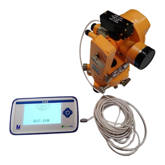
- Page 6 Non-magnetic tool bag 1 set Electronics, including Lemi fluxgate sensor 1 pc Battery charger 1 pc Underplate User manual 1pc Options: non-magnetic tripod and solar filter are available on request 6 / 34 FLM5 DIFlux User Manual rev.0 (January 2024)
- Page 7 Use the power switch to power the FLM5. Upon switching on the magnetometer console, the battery level in Volt is displayed, prompting adequate action if charging is needed (see below “Battery charging”). 7 / 34 FLM5 DIFlux User Manual rev.0 (January 2024)
- Page 8 4. SEND DATA TO PC 5. UTILITY 1. BACKLIGHT ON 2. BACKLIGHT OFF 3. BKL INTENSITY 4. CONTRAST ADJUST To go back in the menu, keep pressing on the OK button for 2 seconds 8 / 34 FLM5 DIFlux User Manual rev.0 (January 2024)
- Page 9 “Menu button OK”. After sync, the display also gives the local WGS84 latitude and longitude and the number of observed satellites. 9 / 34 FLM5 DIFlux User Manual rev.0 (January 2024)
- Page 10 Manual shot can refer to the SUN or to POLARIS Figure 9: manual shot menu The manual method requires the observer to point the telescope to the center of the star and to record the UTC time. 10 / 34 FLM5 DIFlux User Manual rev.0 (January 2024)
- Page 11 Azimuth of the sun/star (+/-180°) in degrees, minutes, seconds to 0.1” at this time and location UTC date UTC time to 0.01s WGS84 local latitude in degrees, minutes, seconds to 0.001” WGS84 local longitude in degrees, minutes, seconds to 0.001” 11 / 34 FLM5 DIFlux User Manual rev.0 (January 2024)
- Page 12 Figure 12: Sunshot add-on is required for automatic sunshot (please contact us if interested) Rasson, J. L., Hendrickx, O., and Marin, J.-L.: Semiautomatic sun shots with the WIDIF DIflux, Geosci. Instrum. Method. Data Syst., 6, 257-261, https://doi.org/10.5194/gi-6-257-2017, 2017. 12 / 34 FLM5 DIFlux User Manual rev.0 (January 2024)
- Page 13 Figure 14: If you press the right key briefly, the display switches to full field mode. (Validated up to +/- 50000nT, even if the display can go higher). Briefly press the right key again to return to normal mode. 13 / 34 FLM5 DIFlux User Manual rev.0 (January 2024)
- Page 14 When 660 data have been recorded, the acquisition will stop and a “memory full” message will be displayed. Figure 16: Write Data Logger shows UTC Time, 1Hz data, battery voltage and memory status 14 / 34 FLM5 DIFlux User Manual rev.0 (January 2024)
- Page 15 “NO”. Using the up arrow key, you can change the answer to “YES”. If you really want to erase, press the “OK” key, and this will erase all logged data. Figure 18: Erase data 15 / 34 FLM5 DIFlux User Manual rev.0 (January 2024)
- Page 16 Windows Device Manager at the line “Ports”. Experiment by manually connecting and disconnecting the console to the USB port and look at which line is added/removed in the Device Manager. 16 / 34 FLM5 DIFlux User Manual rev.0 (January 2024)
- Page 17 We recommend to keep it off when performing measurements under sunny conditions and / or to maximize power autonomy. In order to keep your backlight intensity preference in memory, keep pushing on “OK” until you reach the main menu. 17 / 34 FLM5 DIFlux User Manual rev.0 (January 2024)
- Page 18 The green led indicates that the battery is fully charged (On) The red led indicates the status of the charger. This led will only light up if the blue led is already on. 18 / 34 FLM5 DIFlux User Manual rev.0 (January 2024)
- Page 19 “Fluxgate + Clock” menu until it reaches the desired voltage. You can speed up the discharge by activating the backlight - to store the FLM5 DIFlux in convenient conditions. In particular, temperature should be between 5 °C and 25 °C (between 41°F and 77°F ).
- Page 20 Annex 1: TDJ6E-NM Operating Manual Foreword Thank you for choosing our products! TDJ6E-NM non-magnetic theodolites are special instruments developed by our company for geomagnetism, geology and national defense fields. 20 / 34 FLM5 DIFlux User Manual rev.0 (January 2024)
- Page 21 1.4 When high precision surveying is undertaken an umbrella should be held over the instrument and the tripod to prevent strong sunlight from striking them directly and affecting their performance. 21 / 34 FLM5 DIFlux User Manual rev.0 (January 2024)
- Page 22 It can measure horizontal angle, vertical angle, and distance. Therefore, it can by applied to many fields like fourth class triangulation, traverse survey, various mines, railway, bridge, fairway, urban construction, hydrogeological investigation, farmland, water conservation and transportation. 22 / 34 FLM5 DIFlux User Manual rev.0 (January 2024)
- Page 23 Diameter of vertical circle 76mm Graduation interval 1° (g) Graduation interval of tape measure 1"(c) Estimation reading to 0.1" (0.2°) Reading microscope Magnification of the horizontal system 68X Magnification of the vertical system 65.4X 23 / 34 FLM5 DIFlux User Manual rev.0 (January 2024)
- Page 24 Range of focusing 0.7-∞ Weights and dimensions of instrument Net weight 4.3kg Height of horizontal axis 207mm Dimension 136mm×130mm×286mm Optical system picture (Fig. 1) Instrument structure picture (Fig. 2, Fig3) 24 / 34 FLM5 DIFlux User Manual rev.0 (January 2024)
- Page 25 25 / 34 FLM5 DIFlux User Manual rev.0 (January 2024)
- Page 26 Place the instrument carefully on the tripod then tighten the central screw properly. 5.3 Leveling the instrument Adjust the circular level of the instrument for rough leveling, and then adjust the tubular level for precision leveling. 5.3.1 Adjust the circular level 26 / 34 FLM5 DIFlux User Manual rev.0 (January 2024)
- Page 27 3 to make the bubble move to the middle of the level. Repeat the above described procedure several times so that the offset of the bubble does not exceed the allowance for whatever position the alidade is turned. 27 / 34 FLM5 DIFlux User Manual rev.0 (January 2024)
- Page 28 After finishing the vertical angle measurement, do make the mark “OFF” on the locking knob at the vertical position by turning the knob clockwise. In this case, the compensator is locked safely. 28 / 34 FLM5 DIFlux User Manual rev.0 (January 2024)
- Page 29 For to its use, it is necessary to depress the horizontal rod 1 of the rotary knob 2. At this moment, knob 2 can be pushed in to effect the mutual 29 / 34 FLM5 DIFlux User Manual rev.0 (January 2024)
- Page 30 After adjusting the tubular level, the circular level should be checked immediately. If the bubble of the circular level deviates from the center, adjust the three bleed screws beneath it so that the bubble is centered. 30 / 34 FLM5 DIFlux User Manual rev.0 (January 2024)
- Page 31 6.3.1 Screw the protective cap of the reticule of the telescope in the counter- clockwise direction, and take it off, It is now possible to see the four adjusting screws. 31 / 34 FLM5 DIFlux User Manual rev.0 (January 2024)
- Page 32 Fig. 12. Therefore, the small access cover 20 on Figure 3 must be removed by unscrewing its holding screw. Replace the access cover when the adjustment is completed. The adjusting range is ±2’. 32 / 34 FLM5 DIFlux User Manual rev.0 (January 2024)
- Page 33 Loosen or tighten up four screws until a satisfactory result is obtained. 33 / 34 FLM5 DIFlux User Manual rev.0 (January 2024)
- Page 34 Repeat the above procedure to obtain the better centering. This adjustment should be made at two heights: 1.5 meters and 0.8 meters. After finishing the adjustment, tighten the four screws. 34 / 34 FLM5 DIFlux User Manual rev.0 (January 2024)
Need help?
Do you have a question about the FLM5 DIFlux and is the answer not in the manual?
Questions and answers