
Related Manuals for ASES Security DELTA

Summary of Contents for ASES Security DELTA
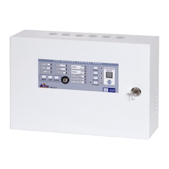
- Page 1 ASES Security Pvt. Ltd. Gas Suppression Control Panel Model : DELTA E.R.T.L., (North) Tested as per IS : 2189/1999 Known for Absolute Reliability... Sold All Over India and Abroad... I N S T R U C T I O N...
- Page 2 e ASES a leading Unit-1 Sahibabad Ind. Area manufacturer of Fire Alarm Systems, Fire Rated Doors, Fire Pump Control Panels, Emergency Lights, PA/VA Systems etc. With a sound infrastructure we manufacture wide range of Control Panels that are used by several institutions.
- Page 3 There are wide ranges of our products according to the Ÿ requirement of customer. We manufacture Conventional as well as Addressable Fire Ÿ Detection & Alarm Systems. ABOUT THE PRODUCT Ÿ ASES is very proud to introduce DELTA the completely digital...
- Page 4 microprocessor based panel in Indian re industry by using the digital technology. This model is for gas suppression control system and it can give you accuracy in its performance. For the ease of user there are visually identify as LED indications. There are control switches in front of panel for handling ALARM ACKNOWLEDGE, LEMP TEST AND RESET.
-
Page 5: Mechanical Construction
manual release, manual abort, disable operations. UP/DOWN switch for delay time setting. External s/w/ fro reset, silence, lamp test. Sov line monitoring facility and line status through LED . LED indication for valve operations and gas discharged. 7-segment display for discharged delay time setting. Key lock for enabling and disabling of control switches. - Page 6 COMMISSIONING Check the all entered wiring is correctly identi ed and also check the cables are free from fault conditions by a multimeter. Connect the external wiring into their respective terminals and ensure the End Of Line (EOL) resistor is placed at the last device of circuit.
-
Page 7: Indicators And Controls
INDICATORS AND CONTROLS INDICATORS : System On: In the Normal only SYSTEM ON green LED will be illuminated. There should on other amber/red LED visual indication or audible tone. Power Fault : When power fault conditions like mains fail the AC FAIL amber LED will glow and SYSTEM ON will be off. - Page 8 MAN REALS: This amber LED will glow when manual release switch is pressed to release the gas. ABORT: This amber LED will glow when abort switch is pressed to stop gas oating. Disable: This amber LED will glow when abort switch is pressed to disable panels operations.
- Page 9 ABORT: This switch is used to stop the Gas oating. When ever this switch is on, timer will stop counting, gas discharge valve will not operate. This switch will turn off after the panel is reset. Abort switch will not operate in manual operation mode of the panel. DISABLE: This switch is used to disable the gas oating part of the panel.
-
Page 10: Technical Data
TECHNICAL DATA Panel Operating Condition Operating Voltage AC Power : 220v AC, 50Hz ± 10% Standby : 24v DC Operating Temperature : 0°C to 50°C Operating Humidity : 95% (non-condensing) Zone Operating Condition Normal Loop Voltage : 23v DC Open Threshold Current : 4.4 mA Short Threshold Current : 35 mA... -
Page 11: Connection Diagram
CONNECTION DIAGRAM: 1 2 3 4 5 6 7 8 9 10 11 12 13 14 15 16 17 18 19 20 21 22 23 24 25 1=zone1 +ve 2=GND 3=zone2 +ve 4=GND 5=Common hooter+ve 6=GND 7=SOV+ve 8=SOV-ve 9=Abort+ve 10=Abort-ve 11=Manual release+ve 12=Manual release-ve 13=Gasdischarged +ve... - Page 12 Single Line Diagram Solenoid Valve output 24v DC 2-Core Wire 2-Core Wire Manual Release Unit 2-Core Wire Manual Abort Unit Common 24V DC Hooter 2-Core Wire Smoke / Multi / Heat Detector and MCP 2-Core for Common Hooter DO’S & DON’T: DO'S: The panel and detectors should be within the temperature range of 0°C to 50°C.
- Page 13 SERVICING / FAULT FINDING If you have any problem read this user manual again & check the center measure for each symptoms listed below: If the problem persists, record down your system number from the warranty card and call us or e-mail asesmail@asesindia.com Symptoms Counter measure 1) System dead...
-
Page 14: Warranty Certificate
WARRANTY CERTIFICATE Dear Customer, Your ASES Security Pvt. Ltd., Fire Alarm System is guaranteed against manufacturing defects of parts and components for a period of 12 months from the date of purchase ......(During this period any items found defective will be repaired at works or through service center. - Page 15 Operating Temp 32° to 120° Fahrenheit This is certify that 2/4/6/8 zone Delta Gas Release Panel supplied as per details has been manufactured by ASES Security Pvt. Ltd. tested as per the provision laid down in IS 2189-1988 and the Electronics Regional Test Laboratory (ERTL).
- Page 16 Mapping Our Growth ASES Security is a registered trademark of ASES Security in India and other countries. © Copyright ASES Security, 2015. All rights reserved. Any unauthorized reproduction or use of logos, design elements is strictly prohibited by law. No part of the compilation may be reproduced in any manner or translated without written permission.
Need help?
Do you have a question about the DELTA and is the answer not in the manual?
Questions and answers