Table of Contents

Summary of Contents for CITO PulseCooling StackPulse
- Page 1 ™ PulseCooling Operation Manual StackPulse Controller ™ N8779 Cty. Rd. X • P.O. Box 90 Watertown, WI 53094 • USA www.pulsecooling.com Phone: (920) 261-2606 • Fax: (920) 261-1350 • E-mail: sales@pulsecooling.com SPC-I-42-A-1...
-
Page 3: Table Of Contents
Table of Contents COOLING PROGRAMS AND PROCESS ALARMS ..23 INTRODUCTION .......5 Cooling Program Selection . -
Page 5: Introduction
Introduction The SPC - StackPulse Controller™ is the newest addition to the PulseCooling in process temperature controls. The SPC has embedded microchip technology for compactness, longevity and high performance. DESCRIPTION OF STACKPULSE CONTROLLER™ The StackPulse Controller™ controls the mold surface, not just the water line. Now you can have a Real Time read out and direct precision control of the mold surface temperature. -
Page 6: Pulsecooling Benefits
PulseCooling results in many benefits: ™ Direct control over MOLD SURFACE TEMPERATURE - not just waterline Quick warm up, only the very molding surface reaches temperature, not the entire mold Higher production quality output - full flow - full velocity cooling with cold water Higher quality parts through gradient dissipation during soak period Allows processor to optimize the molding cycle (visual feed back of mold temperature) Eliminates thermal drift (warpage, sinks, distortion and inconsistent fill) -
Page 7: Frequently Asked Questions
Questions and answers about PulseCooling ™ 1. How does PulseCooling™ improve cycle time? By placing a sensor into the mold and controlling the mold surface temperature. Each molding cycle is cooled with a full flow cooling pulse, timed to match the exact cooling needs of each shot of melt, with coldest water available. -
Page 9: Stackpulse Controller ™ Specifications
StackPulse Controller Specifications ™ Unit Power: 24 VAC, 60 Hz. or 24 VDC Current Draw: 500 mA Display Repeatability: +/- 1 digit Display Units: English or Metric Temperature Inputs Sensor Type: Thermistor Temperature Accuracy: +/- 1 °F Temperature Range: 32° F to 200°F 0°C to 93.33°C Input Sample Rate: Once per 200 ms Display Update:... -
Page 10: Stackpulse Controller 24 Volts Ac/Dc
StackPulse Controller - Surface Mount - 24 VOLT ACDC ™ NOTE: Order Sensors, Manifold w/Hand Valves, and In/Out Fittings separately For sensor selection see page 8 MOLD SURFACE SENSOR 24 VOLTS AC/DC CONNECTION CABLE Stack Pulse Controller Stack Pulse Controller Stack Pulse Controller Stack Pulse Controller Stack Pulse Controller... -
Page 11: Stackpulse Controller 120 / 240 Vac
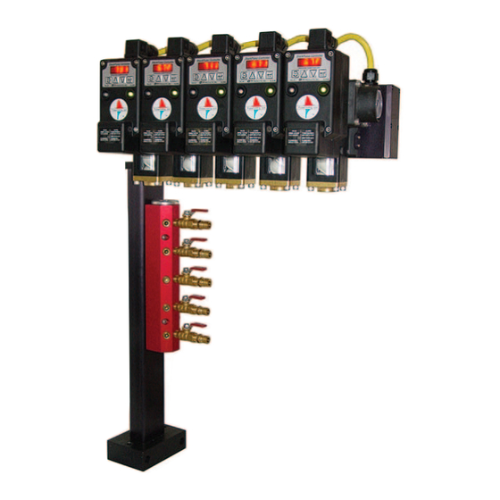
StackPulse Controller - 120 / 240 VOLT AC ™ 19” SENSOR *OPTIONAL CONNECTOR SENSOR CONNECTOR SUPPLY END CAP PRESSURE GAUGE 8.9" POWER AND SENSOR CONNECTOR REMOVE SCREWS TO CLEAN CONTAMINANT (WMA) (SMA) (PMA) SCREEN WALL MOUNT SIDE MOUNT POST MOUNT PRESSURE GAUGE Stack Pulse Controller... -
Page 12: Stackpulse Controller Dimensions
8.58” INLET SIDE 2.625” SQ. 4.42” 3.18” VISUAL FLOW INDICATING 2.0” SQ. TURBINE 3.0” 6.0” 9.0” SINGLE VALVE WITH FLOW INDICATOR SINGLE VALVE WITH FLOW INDICATOR AND TEMPERATURE GAUGE AND PRESSURE GAUGE CITO 1.5” 1" DEGR 4.55” .70” 3.0” 6.40”... -
Page 13: Flow Test-Mold Cooling Channel
Flow Test-Mold Cooling Channel 1. Connect StackValve™ to a water connection 2. Read flow rate through each cooling circuit 3. Flow rate should not vary - if cooling passages are the same. 8 Cavity Mold NOTE: The flow rate is pressure dependent. The following flow rates should be obtained through a cooling channel 10"... -
Page 14: Display Basics
Display Basics Full display shown during start up and shut down. StackPulse Controller Display ™ 4 DIGIT LED DISPLAY Stack Pul s e Control l e r PROCESS TEMPERATURE PROGRAM MENU KEY VALVE PRODUCTS INC ALARM ENTER KEY UP ARROW DOWN ARROW TO INCREASE TO DECREASE... -
Page 15: Mold Connection Diagrams
Mold Connection Diagrams To obtain the highest performance from your StackPulse Controller the sensor should be placed close to the molding part. See CITO Mold Surface Temperature sensor installation on page 22. Single Zone - Series Connection Stack Pul s e Control l e r... -
Page 16: Three Zone Parallel Series Connection
Three Zone - Parallel - Series Connection Stack Pul s e Control l e r Stack Pul s e Control l e r Stack Pul s e Control l e r 120F 120F 110F Advantages: PROCESS TEMPERATURE PROCESS TEMPERATURE PROCESS TEMPERATURE PROG PROG PROG... -
Page 17: Three Zone Parallel Connection
Three Zone Parallel Connection Stack Pul s e Control l e r Stack Pul s e Control l e r Stack Pul s e Control l e r 120F 120F 110F PROCESS TEMPERATURE PROCESS TEMPERATURE PROCESS TEMPERATURE PROG ENTER PROG ENTER PROG ENTER... -
Page 18: Six Zone
Six Zone Parallel Connection FOR ZONE 1 AND 2 USE Advantages: Stack Pulse Controller Stack Pulse Controller Stack Pulse Controller Stack Pulse Controller Stack Pulse Controller Stack Pulse Controller 120F 120F 110F 110F 110F 110F PROCESS TEMPERATURE PROCESS TEMPERATURE PROCESS TEMPERATURE PROCESS TEMPERATURE PROCESS TEMPERATURE PROCESS TEMPERATURE... -
Page 19: Operating Controls
Operating Controls Quick Start Instructions 1. Mount the StackPulse Controller (SPC) in an easily accessible location. 2. Install sensor(s) in tool (see sensor placement guide on page 22). 3. Connect mold sensor(s) to sensor connector located in the back of the StackPulse Controller(s) or to the sensor connector in the StackPulse Controller Buss or Sensor Junction Box. -
Page 20: Program Menu Selection
Program Menu Selection 1. After pressing PROG Button display will toggle menu position and current value. 2. Press PROG button again toggles to the next position. To change hold ARROW key the longer you hold the faster the change 3. To set COOLING SET POINT, press PROG, display reads CSP = COOLING SETPOINT, to change press UP ARROW or DOWN ARROW, display value 115F, to raise set point hold UP ARROW key for 3 seconds, value will increment up. - Page 21 7. To select a PULSE ADVANCE Program, press PROG, display reads PAd4 = PULSE ADVANCE, to save new program in memory, press the ENTER key. Value is now in memory, display reads PAd4. 7.1 To set PERIOD TIME, press PROG, display reads PErt = PERIOD TIME, to change press UP ARROW or DOWN ARROW, display value 14 S, to raise PERIOD TIME hold UP ARROW key for 3 seconds, value will increment up.
-
Page 23: Cooling Programs And Process Alarms
Cooling Programs and Process Alarm Cooling Program Selection After pressing PROG Button display will toggle menu position and current value. To select a FAST COOLING Program, press PROG, display reads POn1 = FAST COOLING, to save new program in memory, press the ENTER key. Value is now in memory, display reads Pon1 PROG PROG 1 To select a PULSE ADVANCE Program, press PROG, display reads PAd4 = PULSE ADVANCE, to save... -
Page 24: Fast Cooling Program
Fast Cooling Program Fast Cooling is used for low temperature mold applications with high cooling requirements. It would be described as a “Direct Response Program”. Fast Cooling will respond to the dynamic temperature wave of the melt. The cooling valve will be “ON”... -
Page 25: Pulse Advance Program
Pulse Advanced Program Pulse Advance will accommodate tools to unable to have sensors installed to “read” the mold surface temperature. An “Internal or External Wet Probe” is installed in the outgoing water line. These probe will sense the outgoing temperature of the water, thus receiving the information on the amount of heat the water is picking up going through the mold. -
Page 26: Under Set Point Alarm
Process Alarms Under Set Point Alarm To set UNDER SET POINT, press PROG, display reads USP = UNDER SETPOINT, to change press UP ARROW or DOWN ARROW, display value 105F, to raise set point hold UP ARROW key for 3 seconds, value will increment up. -
Page 27: System Components
System Components Temperature Sensor SPC temperature sensor are thermistors-based sensors. Those are sensor that change their resistance as the temperature changes. As the temperature goes up their internal resistance goes down and as their temperature goes down their resistance goes up. Their resistance is 20, 000 ohms at 77 Fahrenheit. -
Page 28: Mold Water Temperature Sensor
Mold Water Temperature Sensor The second is called a “ Wet Probe”. Those sensors measure the temperature rise in the water as the water is picking up the energy coming out of the mold. From this information gained, the control algorithms can accurately control the mold surface temperature. The “... -
Page 29: Sensor Selection
Sensor Selection This wide selection enables you to customize any of your existing molds with Internal Wet Probes. SPRING BEAD PROBE 3/16" WITH 3/16" SENSOR SPRING BEAD INTERNAL WET PROBE SPRING BEAD GUIDE TUBE FOR PROBE 3/16" 3-18" LONG PROBE 1/8" 90 DEGR. -
Page 30: Sensor Selection Guide
Sensor Selection Guide ARMORED MINI PROBE 1/8", 1/8" x .5" LONG TIP SPRING BEAD PROBE 1/8" 1/4-28 DWG.AMP-1200 DWG.SBP-1102 DWG.AMP-1220 DWG.SBP-1202 SBP-2-20-12 AMP-2-20-006 (1/8" DIA 6" LONG) SBP-2-20-24 AMP-2-20-012 (1/8" DIA 12" LONG) SPRING BEAD PROBE 3/16" AMP-2-20-024 (1/8" DIA 24" LONG) DWG.SBP-1103 AMP-2-20-048 (1/8"... -
Page 31: Sensor Junction Box
Sensor Junction Box The StackPulse Controller uses mold or platen mounted Junction Boxes to provide an easy sensor connection. Stationary mold halve may have sensor connected to zone 1 and 2; 3, 4, 5 should not be connected. Movable may have sensor connected to sensor 3, 4, and 5 ; 1 and 2 should not be connected. Never connect 2 sensors to the same zone;... -
Page 32: Spc 3D Assembly
SPC CONTROLLER COVER ASS’Y SPC-1424 PILOT VALVE COIL ASSEMBLY SV-9310-XX FOR CUSTOM TOP ASS'Y (10) 10-32 X 1-1/2" ST ST SHCS CONTACT FACTORY CLIP RING S36-10-32-48 R48-500-0565 WAVE WASHER # PV-3314 (6) WASHER PISTON STEM PV-1220-DC W20-C10-S-7 # 10 STST PV-1240-AC - YELLOW HEX HOLE TOP COVER ASS’Y PISTON / SLEEVE ASSY PV-1420-DC... -
Page 34: Replacement Parts
Replacement Parts StackValve Digital Top for StackPulse Controller ™ ™ COVER WITH PILOT VALVE ASS’Y PART NO. CONNECTOR SENSOR PURGE VOLT SDT-2624 X-ALL 24V ACDC SDT-3824 MICRO - 12mm 24V ACDC SDT-4824 MINI - 20mm 24V ACDC SDT-5124 24V ACDC Module without End Components StackValve , Stack Controller... - Page 35 Replacement Parts Diaphragm Rebuild Kit - StackValve , StackController ™ ™ StackPulse Controller ™ Valve Guide and Diaphragm Assembly Standard Closing Speed SV-9120 Slow Closing Speed (Blue Instruction Sheet) SV-9089 Pilot Valve Assembly for StackValve , StackController ™ ™ StackPulseController ™...
-
Page 36: Trouble Shooting Guide
Trouble Shooting Guide Your StackPulse Controller™ have been designed to provide years of trouble free operation and service. However, in the event a problem does arise check the following: Over Temperature Alarm If the Alarm light flash RED for OVER Temperature: CAUTION !!! Do not turn up the setpoint just to avoid this alarm indication. -
Page 37: Sensor Test
Sensor Test The StackPulse Controller unit utilizes thermistor sensor, which are resistive devices. Typical resistance reading would be 20, 000 Ohms at 77 Degree F. The resistance will go up as the temperature gets colder, and the resistance will go down if the temperature is warmer. If you are experiencing problems with sensor please go through the following steps to attempt to resolve the problems. -
Page 38: Turbine Problems
Read out problem: • Check for loose cable connections Turbine Problems • Turbine does not turn freely— clean turbine If you send the units to the service department please have the following information included: • Model Number of StackPulse Controller™ •... -
Page 39: Appendix
Appendix Mold Surface Temperature Sensor ZONING WILL OPTIMIZE THE MOLD PERF ORMANCE AND WIDEN THE PROCESS WINDOW A MOLDING CYCLE IS LIMITED BY THE SLOWEST ZONE OR AREA EACH MOLD SECTION HAS VARIOUS HEAT LOADS (HOT / COLD AREAS ) STATIONARY (CAVITY) Hot Runner Sprue Cooling... -
Page 40: Sensor Position And Distance From Surface
Sensor Position and Distance from Surface Sensor connection 1/100 Resolution Ohm @ 77ºF = 20 K As temperature increases resistance will go down 1. Connect sensor to 2 digit Ohm meter 2. Wait to get a stable reading 3. Rub thumb over surface where sensor is located Push thumb firmly on sensing area 4. -
Page 41: Performance And Product Warranty
Our liability under this warranty is limited to the repair or replacement of the product, after careful inspection by Cito Products, Inc. This warranty does not cover obvious abuse or misuse of the product. Responsibility as to the intended use and suitability of the products rests entirely with the user. - Page 42 N8779 Cty. Rd. X • P.O. Box 90 Watertown, WI 53094 • USA www.pulsecooling.com Phone: (920) 261-2606 • Fax: (920) 261-1350 • E-mail: sales@pulsecooling.com...
Need help?
Do you have a question about the PulseCooling StackPulse and is the answer not in the manual?
Questions and answers