
Summary of Contents for Camfil CamCleaner CCH2000
- Page 1 Installation, Operation, and Maintenance Manual CamCleaner Horizontal System M38000157 IOM Manual, CamCleaner Horizontal Version 3 October 2020 www.camfil.us...
-
Page 2: Table Of Contents
Disclaimer Camfil is committed to providing air filtration products which meet or exceed our customer’s expectations. We are dedicated to a corporate-wide policy of continual improvements as a means of ensuring our leadership position in the air filtration marketplace. Before proceeding with installation, operation, or maintenance, review manual and all safety procedures with your company’s safety personnel. -
Page 3: Product Information
Note: To prevent shortening its service life, the CamCleaner capture may be difficult. Camfil CamCarb cylinders are an should not be used during the finishing phases of construction. optional stage of filtration to control molecular contaminants. -
Page 4: System Installation
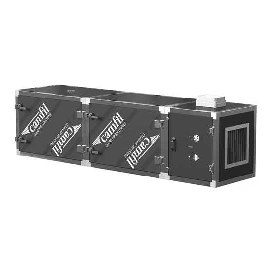
Junction Box (customer wiring connection) Fan Indicator Light Air Flow (direction) Air Inlet Filter Indicator Light Hinged Access Doors Type F (Filter) Module Type C (Cylinder) Module Type M (Motor/Fan) Module M38000157 IOM Manual, CamCleaner Horizontal Version 3 October 2020 www.camfil.us... -
Page 5: System Layout
AC/Hr = Air changes per hour 60 = Minutes per hour Illustrations of unducted unit placements for a circular air pattern and a cross-bay air pattern Consult a Camfil representative to assist with proper system placement. System Installation and Preparation Module Connections CamCleaner systems are shipped as individual modules ready for assembly. -
Page 6: Module Security Straps
Remove supplied outlet louver by removing its fasteners. (save fasteners for Step 3) Fasten directional outlet using its supplied fastener kit. Reattach louver to directional outlet using the saved fasteners. Part Numbers CCH2000, M21K00012 CCH4000, M21K00013 M38000157 IOM Manual, CamCleaner Horizontal Version 3 October 2020 www.camfil.us... -
Page 7: System Suspension Hanging Points
Type F (Filter) Module + Type C (Cylinder) Module + Type M (Motor/Fan) Module Support Rods = Strut Channel Attachment Point (below unit) (4 EA TYP) 48” Clearance Access Required Entire Length Bottom View M38000157 IOM Manual, CamCleaner Horizontal Version 3 October 2020 www.camfil.us... - Page 8 Type F (Filter) Module + Type C (Cylinder) Module + Type M (Motor/Fan) Module = Support Connection Location Support Rods (8 EA TYP) Top View 48” Clearance Access Required Entire Length M38000157 IOM Manual, CamCleaner Horizontal Version 3 October 2020 www.camfil.us...
-
Page 9: Optional Oil Mist Kits
Installation, Operation, and Maintenance Manual CamCleaner Horizontal System Optional Oil Mist Kits P/N M21K00008 Oil Kit Assembly Without Jar Installation Instructions M38000157 IOM Manual, CamCleaner Horizontal Version 3 October 2020 www.camfil.us... -
Page 10: Power Requirements
CCH2000 240VAC/1PH 1335 Watts 5.6 Amps CCH2000 240VAC/3PH 1977 Watts 5.0 Amps CCH2000 480VAC/3PH 2500 Watts 3.2 Amps CCH4000 240VAC/3PH 3618 Watts 9.2 Amps CCH4000 480VAC/3PH 3420 Watts 4.6 Amps M38000157 IOM Manual, CamCleaner Horizontal Version 3 October 2020 www.camfil.us... -
Page 11: Power Inlet Location
Junction Box (customer wiring connection) Inside Junction Box with cover removed Terminal Fuse Block: Qty (2) Fuses for Single Phase Power Qty (3) Fuses for Three Phase Power Type M (Motor/Fan) Label Example M38000157 IOM Manual, CamCleaner Horizontal Version 3 October 2020 www.camfil.us... -
Page 12: Field Wiring Schematics
Refer to wiring diagrams (below) for optional field rewiring. Refer to the transformer wiring legend (right) for correct wire color when field wiring is required for voltages other than factory default. Single Phase Power Wiring Diagrams M38000157 IOM Manual, CamCleaner Horizontal Version 3 October 2020 www.camfil.us... - Page 13 There are no voltage options available for the 480VAC / 3Ø motor module. This unit will be wired directly from the factory for that voltage. Three Phase Power Wiring Diagrams M38000157 IOM Manual, CamCleaner Horizontal Version 3 October 2020 www.camfil.us...
-
Page 14: Outlet Louver Setup
It is advised to use a gasketed ductwork connection to prevent air bypass. WARNING: Ensure attached ductwork is supported independently of the CamCleaner system. Recommended fastener spacing for ductwork to 50mm tubular frame connection CCH2000 Outlet Flange Detail CCH4000 Outlet Flange Detail M38000157 IOM Manual, CamCleaner Horizontal Version 3 October 2020 www.camfil.us... -
Page 15: System Control Settings
20 seconds. The actual delay time is set using the center adjustment (Blue timing trimmer). Range is 1 Pressure Switch – 20 seconds). Factory default is 10 seconds. M38000157 IOM Manual, CamCleaner Horizontal Version 3 October 2020 www.camfil.us... -
Page 16: Air Flow Setting/Programming Instructions
Factory Default Settings WARNING: The following settings are used by Camfil to set up your CamCleaner for proper operation. The Owner is encouraged to avoid performing other Controller adjustments. Failure to do so may result in unsatisfactory operation or damage to your CamCleaner, which may void the warranty. -
Page 17: Pressure Setting Recommendations Based On Filter Configuration
Installation, Operation, and Maintenance Manual CamCleaner Horizontal System Pressure Setting Recommendations Based on Filter Configuration Use the table to determine the recommended total system final pressure drop based on your filter combination. M38000157 IOM Manual, CamCleaner Horizontal Version 3 October 2020 www.camfil.us... -
Page 18: Operating Your Camcleaner
Close the filter module access door and secure door handles. Reverse steps for removing prefilter. Do not remove prefilter while system is powered ON and in operation. Quantity of (2) prefilters are required for CC4000 models. M38000157 IOM Manual, CamCleaner Horizontal Version 3 October 2020 www.camfil.us... - Page 19 Replace the filter as noted in Step 5 (above). Camfil recommends that you have a full replacement set of filters on hand. You can exchange filters using your spare set. Once removed, you can put your CamCleaner back in service quickly and wash the dirty filters before replacing them at the next service interval.
- Page 20 Reverse steps for removing the bag filter. Do not remove the bag filter while system is powered ON and in operation. When using bag filters in a CCH4000, a quantity of (2) bag filters are required. See page 21 for illustration. M38000157 IOM Manual, CamCleaner Horizontal Version 3 October 2020 www.camfil.us...
- Page 21 Reverse steps for removing post filter. Do not remove post filter while system is powered ON and in operation. When using post filters in a CCH4000, a quantity of (2) post filters are required. Insert Post Filter into Tracks Filter Installed M38000157 IOM Manual, CamCleaner Horizontal Version 3 October 2020 www.camfil.us...
-
Page 22: Standard Features
10. Reverse steps for removing the cylinder filters. Do not remove cylinder filters while system is powered ON and in operation. Identify holding frame mount Insert cylinder and firmly press against holding Identify SST bayonet stubs frame Manually rotate cylinder clockwise to Cylinder filters installed secure into place Standard Features M38000157 IOM Manual, CamCleaner Horizontal Version 3 October 2020 www.camfil.us... -
Page 23: Spare Parts List
Secure panel clamp stops are provided on the motor module and can be loosened using a 4mm hex key (in assembly kit) and rotated 90° to release the door panel. Recommended Spare Parts List M38000157 IOM Manual, CamCleaner Horizontal Version 3 October 2020 www.camfil.us... -
Page 24: Optional Equipment
See pages 9-10 for installation instructions. Silencing Accessories Silencing options are available if needed. Send inquiries to Sales-WA@camfil.com. Adjustable Feet In lieu of suspension options, the system can be supported by adjustable feet (part number M21K00002 - 4 EA per kit) when placed on a level, structurally-sound platform. -
Page 25: Maintenance Inspection
Camfil USA, Inc. published specifications and submittal drawings included in the purchase agreement. The term of this warranty shall be one year from date of shipment from Camfil. There are no other warranties that extend beyond this description. -
Page 26: Troubleshooting
FOR INLET AND OUTLET OBSTRUCTIONS → OIL COLLECTION BOTTLE IS OIL NOT DRAINING → EMPTY OIL COLLECTION BOTTLE FULL → OIL DRAIN IS PLUGGED → UNCLOG DRAIN → P-TRAP IS PLUGGED → UNCLOG P-TRAP M38000157 IOM Manual, CamCleaner Horizontal Version 3 October 2020 www.camfil.us... - Page 27 ERROR PEAK CURRENT 17 x SEVENTEEN RED FLASHES TEMPERATURE ALARM * CONSECUTIVE UNINTERRUPTED LED FLASHES LED flashes may also be observed on the fan motor housing viewable through the outlet louver. M38000157 IOM Manual, CamCleaner Horizontal Version 3 October 2020 www.camfil.us...
-
Page 28: Contact Information
Belgium • France • Germany • Ireland • Malaysia • Sweden • Switzerland • United Kingdom Camfil USA, Inc. Camfil has a policy of continuous research, development United States Tel: (973) 616-7300 Fax: (973) 616-7771 and product improvement. We reserve the right to Canada Tel: (450) 629-3030 Fax: (450) 662-6035 change designs and specifications without notice.
Need help?
Do you have a question about the CamCleaner CCH2000 and is the answer not in the manual?
Questions and answers