
Summary of Contents for Columbus McKinnon Magnetek Flex EX2
- Page 1 Flex EX2 Radio Remote Control Equipment Instruction Manual Part Number: 191-50000-M100 R01 May 2024 ©Copyright 2024 Magnetek...
- Page 2 This manual may not be reproduced in whole or in part by any means whatsoever without the expressed written permission of the Columbus McKinnon Corporation. Flex EX2 Instruction Manual...
- Page 3 PRODUCT SAFETY INFORMATION Magnetek, Inc. offers a broad range of radio remote control products, control products, adjustable frequency drives, and industrial braking systems for overhead material handling applications. This manual has been prepared by Magnetek to provide information and recommendations for the installation, use, operation and service of Magnetek’s material handling products and systems (Magnetek Products).
-
Page 4: Table Of Contents
Table of Contents Introduction............................6 Radio Controlled Safety ........................7 Critical Installation Considerations ....................8 General............................8 Persons Authorized to Operate Radio Controlled Cranes ............... 8 Safety Information and Recommended Training for Radio Controlled Equipment Operators ..9 Transmitter Unit ..........................10 Pre-Operation Test ........................ - Page 5 System Status Light Indications ..................... 80 Transmitter Status Indications ....................... 80 Receiver Status Indications ......................81 Receiver Power Indications ......................81 Receiver COM Indications ......................81 General Specifications ........................82 Declaration of Conformity........................ 83 Appendix A Tandem Systems ......................... 84 Apx A1.Tandem System Operation ......................84 Apx A2.Tandem System Operation ......................
-
Page 6: Introduction
1 Introduction The Flex EX2 radio remote control systems are designed for control of industrial equipment and machinery such as overhead traveling cranes, jib cranes, gantry cranes, tower cranes, electric hoists, winches, monorails, conveyor belts, mining equipment and other material handling equipment where wireless control is preferred. -
Page 7: Radio Controlled Safety
2 Radio Controlled Safety WARNINGS and CAUTIONS Throughout this document WARNING and CAUTION statements have been deliberately placed to highlight items critical to the protection of personnel and equipment. WARNING WARNING indicates a potentially hazardous situation which, if not avoided, could result in death or serious injury. -
Page 8: Critical Installation Considerations
2.1 Critical Installation Considerations WARNING Prior to installation and operation of this equipment, read and develop an understanding of the contents of this manual and the operation manual of the equipment or device to which this equipment will be interfaced. Failure to follow this warning could result in serious injury or death and damage to equipment. -
Page 9: Safety Information And Recommended Training For Radio Controlled Equipment Operators
Radio controlled equipment should not be operated by any person with insufficient eyesight or hearing or by any person who may be suffering from a disorder or illness that may cause them to lose control of the equipment, is taking any medication that may cause loss of equipment control, or is under the influence of alcohol or drugs. -
Page 10: Transmitter Unit
• operate any material handling equipment using a damaged controller because the unit may be unsafe • operate manual motions with other than manual power • operate radio controlled equipment when low battery indicator is on WARNING The operator should not attempt to repair any radio controller. If any product performance or safety concerns are observed, the equipment should immediately be taken out of service and be reported to the supervisor. -
Page 11: Batteries
2.7 Batteries WARNING Know and follow proper battery handling, charging and disposal procedures. Improper battery procedures can cause batteries to explode or do other serious damage. Failure to follow this warning could result in serious injury or death and damage to equipment. 2.7.1 Changing Batteries Change transmitter batteries (“AA”... -
Page 12: General System Information
3 General System Information 3.1 General Operation 1. Reset the STOP button located on the top left hand corner of the transmitter by rotating it clockwise or counterclockwise; the button will pop up. Turn on the transmitter power by inserting the power switch key and rotating to the ON ( I ) position. - Page 13 6. After 5 minutes of inactivity (pushbutton not pressed) the receiver MAIN relays are temporarily disconnected (see Section 4.1.7 Transmitter Inactivity Timer Settings on page 33). Press any pushbutton or execute the START command to resume operation (see Section 4.1.9 Transmitter Start Function Settings on page 34).
-
Page 14: Transmitter
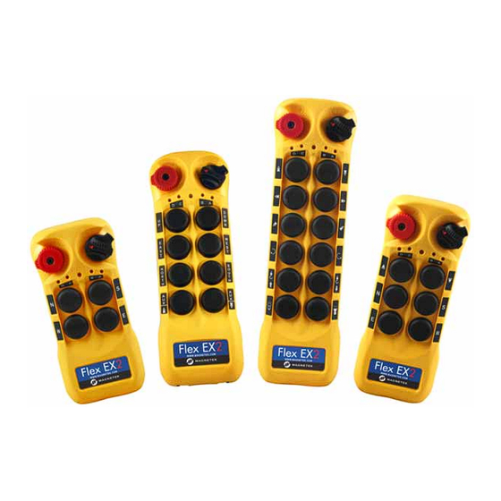
3.2 Transmitter 3.2.1 External Illustrations 4-Button Front 6-Button Front 8-Button Front 12-Button Front 12-Button Back STOP Button Pushbutton 8 (PB8) Power Key Switch Pushbutton 9 (PB9) Status LED Indicator Pushbutton 10 (PB10) Pushbutton 1 (PB1) Pushbutton 11 (PB11) Pushbutton 2 (PB2) Pushbutton 12 (PB12) Pushbutton 3 (PB3) TAC* and Inductive Charging... -
Page 15: Internal Illustrations
3.2.2 Internal Illustrations 4-Button Top 6-Button Top 8-Button Top 12-Button Top 12-Button Back RF Transceiver Board Infrared Sensors Encoder Board I-Chip Slot Status LED Indicator Function Dipswitch A/B/C/D LED Indicators Programming Port* * The programming port is only used for updating the transmitter firmware. It is not used with the infrared (IR) programmer. -
Page 16: Receiver
3.3 Receiver 3.3.1 4EX2 Receiver 3.3.1.1 External and Internal Illustrations Mounting Bracket Release External RP-TNC Antenna Port COM LED Indicator Decoder Board Status LED Indicator RF Transceiver Board Power LED Indicator INT/EXT Antenna Jumpers Output Relay LED Indicators Programming Port Infrared Sensors Function Dipswitches Remote Pairing Button... - Page 17 3.3.1.2 Output Relay Contact Diagram FWD (PB1) REV (PB2) FWD 2 REV 2 FWD (PB3) REV (PB4) FWD 2 REV 2 * For 9-36VDC power supply, wire #1 corresponds to the negative charge (-) and wire #3 corresponds to the positive charge (+). Wire #2 is for GROUND.
-
Page 18: 6Ex2 Receiver
3.3.2 6EX2 Receiver 3.3.2.1 External and Internal Illustrations Mounting Bracket Release External RP-TNC Antenna Port COM LED Indicator Decoder Board Status LED Indicator RF Transceiver Board Power LED Indicator INT/EXT Antenna Jumpers Output Relay LED Indicators Programming Port Infrared Sensors Function Dipswitches Remote Pairing Button Function Jumpers... - Page 19 3.3.2.2 Output Relay Contact Diagram Flex 6EX2 COM 1 COM 3 FWD (PB1) FWD (PB5) REV (PB6) REV (PB2) FWD 2 FWD 2 REV 2 REV 2 COM 2 FWD (PB3) REV (PB4) FWD 2 REV 2 * For 9 - 36VDC power supply, wire #1 corresponds to the negative charge (-), wire #3 corresponds to the positive charge (+), and wire #2 is for GROUND.
-
Page 20: 8Ex2 Receiver
3.3.3 8EX2 Receiver 3.3.3.1 External and Internal Illustrations External TNC Antenna Port Decoder Board COM LED Indicator RF Transceiver Board Status LED Indicator INT/EXT Antenna Jumpers Power LED Indicator Programming Port Output Relay LED Indicators Function Dipswitches Infrared Sensors Function Jumpers Remote Pairing Button Channel Dipswitch System Information... - Page 21 3.3.3.2 Output Relay Contact Diagram COM 3 COM 1 FWD (PB1) FWD (PB5) REV (PB2) REV (PB6) FWD 2 FWD 2 REV 2 REV 2 COM 2 COM 4 FWD (PB3) FWD (PB7) REV (PB4) REV (PB8) FWD 2 FWD 2 REV 2 REV 2 * For 9 - 36VDC power supply, wire #1 corresponds to the negative charge (-), wire #3 corresponds to the positive charge (+), and...
-
Page 22: 12Ex2 Receiver
3.3.4 12EX2 Receiver 3.3.4.1 External and Internal Illustrations External TNC Antenna Port Decoder Board COM LED Indicator RF Transceiver Board Status LED Indicator INT/EXT Antenna Jumpers Power LED Indicator Programming Port Output Relay LED Indicators Function Dipswitches Infrared Sensors Function Jumpers Remote Pairing Button Channel Dipswitch System Information... - Page 23 3.3.4.2 Output Relay Contact Diagram COM 1 COM 3 FWD (PB1) FWD (PB5) REV (PB2) REV (PB6) FWD 2 FWD 2 REV 2 REV 2 COM 2 COM 4 FWD (PB3) FWD (PB7) REV (PB4) REV (PB8) FWD 2 FWD 2 REV 2 REV 2 COM 5...
-
Page 24: 4Ex2-Mrx And 6Ex2-Mrx
3.3.5 4EX2-MRX and 6EX2-MRX NOTE: MRX receiver is not available with the EX2 transmitter in the U.S., Mexico, and Canada. 3.3.5.1 External Illustration External TNC Antenna Port Mounting Bracket Release COM LED Indicator RF/Decoder Board Status LED Indicator Internal Antenna Power LED Indicator INT/EXT Antenna Jumpers Output Relay LED Indicators... - Page 25 3.3.5.2 Output Relay Contact Diagram (4EX2-MRX) NOTE: MRX receiver paired with an EX2 transmitter is not available in the U.S., Mexico, and Canada. Flex 4EX2 K27B K27A MAIN FWD (PB1) REV (PB2) FUNC F/R 2 FWD (PB3) Power Transformer REV (PB4) F/R 2 * For 9-36VDC power supply, wire #1 corresponds to the negative charge (-) and wire #3 corresponds to the positive charge (+).
-
Page 26: Function Settings
4 Function Settings 4.1 Transmitter 4.1.1 Transmitter Firmware Version 1. Rotate the power switch key to the OFF ( 0 ) position. 2. With the STOP button elevated, press and hold PB1 and PB3 at the same time. 3. Rotate the power switch key to the ON ( I ) position. 4. -
Page 27: Transmitter Channel Settings
4.1.3 Transmitter Channel Settings Unassigned Channel Scheme (no preset system channel) – Default Setting When both transmitter and receiver are set to unassigned channel scheme (no preset channel), the system automatically searches and locks onto a free and uninterrupted channel at every transmitter startup. - Page 28 5. Change transmitter channel by pressing PB1 to increment the units (+1) and PB2 to increment the tens (+10). For example, press PB2 two times and then PB1 four times for channel 24 (Status LED blinks 2 greens and 4 reds). Make sure the newly selected channel appears on the Status LED before proceeding to the next step.
-
Page 29: Remote Pairing
4.1.4 Remote Pairing Transmitter-to-Transmitter Pairing: 1. Rotate the power switch key on transmitter(s) to the OFF ( 0 ) position. 2. With the STOP button elevated, press and hold PB1 and PB3 at the same time. 3. Rotate the power switch key to the ON ( I ) position. 4. - Page 30 Receiver-to-Transmitter Pairing (4/6/8/12EX2): 1. Rotate the power switch key to the OFF ( 0 ) position. 2. With the STOP button elevated, press and hold PB1 and PB3 at the same time. 3. Rotate the power switch key to the ON ( I ) position. 4.
-
Page 31: I-Chip
Receiver-to-Transmitter Pairing (4/6EX2 MRX): NOTE: MRX receiver paired with an EX2 transmitter is not available in the U.S., Mexico, and Canada. S2 dipswitch position 10 set to “0” (down): After the transmitter enters the Remote Pairing mode, output receiver data by pressing and holding the PAIRING button located on the receiver cover and receive data by pressing and holding PB3 on the transmitter, both at the same time. -
Page 32: Transmitter Output Power Settings
NOTE: 863-869 MHz and 921-927 MHz (Australia only) Flex EX2 CE transmitters are not compatible with GEN1 Flex EX receivers even if an I-Chip is inserted into the transmitter. NOTE: All settings in this manual are no longer applicable once an I-Chip is inserted into a Flex EX2 transmitter. -
Page 33: Transmitter Inactivity Timer Settings
4.1.7 Transmitter Inactivity Timer Settings Set how long the system waits to enter the sleep mode when the transmitter is not in use (pushbutton not pressed). When transmitter goes into sleep mode the receiver MAIN relays are deactivated. Default is 5 minutes. -
Page 34: Transmitter Start Function Settings
4.1.9 Transmitter Start Function Settings When the transmitter goes into sleep mode the system is temporarily deactivated (MAIN relays opened). Execute the START command (default) or press any pushbutton to wake up the system (MAIN relays closed). Dipswitch Function Settings START xxxxxxxxx0 Reactivation... - Page 35 5. The Status LED displays current pushbutton function setting with orange, green and red blinks. An orange blink represents the hundreds (+100), a green blink represents the tens (+010), a red blink represents the units (+001), and solid orange represents no function (000). For example, 1 orange blink followed by 2 green blinks and 5 red blinks is pushbutton function no.
- Page 36 4.1.12.2 Toggled Pushbutton with LED Indication – Standard Right/Left Pushbutton Configuration – 6EX2 and 6EX2-MRX NOTE: MRX receiver paired with an EX2 transmitter is not available in the U.S., Mexico, and Canada. Set pushbutton toggled function (latching output relay) with LED indications. LED 1 - 4 shown inside the shaded box illustrates which LED on the transmitter lights up when the designated pushbutton is pressed.
- Page 37 4.1.12.3 Toggled Pushbutton with LED Indication – Standard Right/Left Pushbutton Configuration – 8EX2 Set pushbutton toggled function (latching output relay) with LED indications. LED 1 - 4 shown inside the shaded box illustrates which LED on the transmitter lights up when the designated pushbutton is pressed.
- Page 38 4.1.12.4 Toggled Pushbutton with LED Indication – Standard Right/Left Pushbutton Configuration – 12EX2 Set pushbutton toggled function (latching output relay) with LED indications. LED 1 - 4 shown inside the shaded box illustrate which LED on the transmitter lights up when the designated pushbutton is pressed.
- Page 39 4.1.12.5 A/B Pushbutton Select with LED Indication – Standard Right/Left Pushbutton Configuration – 4EX2 There are 5 different types of A/B selector sequence available. Choose one that is most suitable for your application. See Section 3.3.1.2 on page 17 for output relay contact diagrams. Type-A selector sequence: A →...
- Page 40 Function Display Type Number 2 Orange + 6 Greens Normal Normal E/1&2 C/3&4 2 Orange + 6 Greens + 1 Red Normal Normal E/1&2 D/3&4 * PB1…PB4 → Pushbutton number. * Normal → Normal momentary contact. * A/1&2 - E/3&4 → A/B pushbutton select function with designated LED indication. 4.1.12.6 A/B Pushbutton Select with LED Indication –...
- Page 41 4.1.12.7 A/B Pushbutton Select with LED Indication – Standard Right/Left Pushbutton Configuration – 8EX2 There are 5 different types of A/B selector sequence available. Choose one that is most suitable for your application. See Section 3.3.3.2 on page 21 for output relay contact diagrams. Type-A selector sequence: A →...
- Page 42 Function Display Type Number 2 Orange + 6 Greens + 6 Reds Normal Normal E/1&2 C/3&4 2 Orange + 6 Greens + 7 Reds Normal Normal E/1&2 D/3&4 * PB5…PB8 → Pushbutton number. * Normal → Normal momentary contact. * A/1&2 - E/3&4 → A/B pushbutton select function with designated LED indication. 4.1.12.8 A/B Pushbutton Select with LED Indication –...
- Page 43 Function Display Type PB10 PB11 PB12 Number 8 Greens + 1 Red C/1&2 D/3&4 Normal Normal 8 Greens + 2 Reds D/1&2 D/3&4 Normal Normal 8 Greens + 3 Reds Normal Normal A/1&2 Normal 8 Greens + 4 Reds Normal Normal B/1&2 Normal...
- Page 44 Function Display Type PB10 PB11 PB12 Number 2 Orange+ 7 Greens + 8 Reds Normal Normal E/1&2 C/3&4 2 Orange+ 7 Greens + 9 Reds Normal Normal E/1&2 D/3&4 * PB9…PB12 → Pushbutton number. * Normal → Normal momentary contact. * A/1&2 - E/3&4 →...
- Page 45 4.1.12.10 Toggled Pushbutton with LED Indication – Inline Top/Bottom Pushbutton Configuration – 6EX2 Set pushbutton toggled function (latching output relay) with LED indications. LED 1 - 4 shown inside the shaded box illustrates which LED on the transmitter lights up when the designated pushbutton is pressed. See Section 4.2.4 on page 66. Function Display Type Number...
- Page 46 4.1.12.11 Toggled Pushbutton with LED Indication – Inline Top/Bottom Pushbutton Configuration – 8EX2 Set pushbutton toggled function (latching output relay) with LED indications. LED 1 - 4 shown inside the shaded box illustrates which LED on the transmitter lights up when the designated pushbutton is pressed. See Section 4.2.4 on page 66 for jumper settings.
- Page 47 4.1.12.12 Toggled Pushbutton with LED Indication – Inline Top/Bottom Pushbutton Configuration – 12EX2 Set pushbutton toggled function (latching output relay) with LED indications. LED 1 - 4 shown inside the shaded box illustrate which LED on the transmitter lights up when the designated pushbutton is pressed. See Section 4.2.4 on page 66 for jumper settings.
- Page 48 4.1.12.13 A/B Pushbutton Select with LED Indication - Inline Top/Bottom Pushbutton Configuration – 4EX2 There are 5 different types of A/B selector sequence available. Choose one that is most suitable for your application. See Section 3.3.1.2 on page 17 for output relay contact diagrams. Type-A selector sequence: A →...
- Page 49 Function Display Type Number 2 Orange + 8 Greens + 3 Reds Normal Normal E/1&2 C/3&4 2 Orange + 8 Greens + 4 Red Normal Normal E/1&2 D/3&4 * PB1…PB4 → Pushbutton number. * Normal → Normal momentary contact. * A/1&2 - E/3&4 → A/B pushbutton select function with designated LED indication. 4.1.12.14 A/B Pushbutton Select with LED Indication –...
- Page 50 Function Display Type Number 1 Orange + 2 Greens Normal Normal A/1&2 D/3&4 + 2 Reds 1 Orange + 2 Greens Normal Normal B/1&2 B/3&4 + 3 Reds 1 Orange + 2 Greens Normal Normal B/1&2 C/3&4 + 4 Reds 1 Orange + 2 Greens Normal Normal...
- Page 51 4.1.12.15 A/B Pushbutton Select with LED Indication – Inline Top/Bottom Pushbutton Configuration – 12EX2 There are 5 different types of A/B selector sequence available. Choose one that is most suitable for your application. See Section 4.2.4 on page 66 for jumper settings and Section 3.3.4.2 on page 23 for output relay contact diagrams.
- Page 52 Function Display Type PB10 PB11 PB12 Number 8 Greens + 9 Reds Normal Normal Normal C/3&4 9 Greens Normal Normal Normal D/3&4 1 Orange + 4 Greens + 7 Reds Normal Normal A/1&2 A/3&4 1 Orange + 4 Greens + 8 Reds Normal Normal A/1&2...
-
Page 53: Receiver
4.2 Receiver 4.2.1 Receiver Channel Settings For the 4/6/8/12EX2, set the receiver channel by configuring the channel dipswitch located on the decoder board, which is mounted to the inside of the front half of the enclosure. For the 4EX2-MRX and 6EX2- MRX, set the receiver channel by configuring the S3 channel dipswitch located on the RF/decoder board. -
Page 54: Output Relay Configurations
4.2.2 Output Relay Configurations 4.2.2.1 Output Relay Types 1. 2 output relays per motion – single speed only Output relays with Forward (F) and Reverse (R) 1st speed only. 2. 3 output relays per motion – shared 2nd speed output relay Output relays with Forward 1st speed (F1), Reverse 1st speed (R1) and Forward/Reverse 2nd speed (F/R2). - Page 55 4.2.2.2 Output Relay Actions at 2nd Speed 1. 3 output relays configuration with Closed/Closed contact at 2nd speed F1 (or R1) output relay closed at 1st speed and F1 + F/R2 (or R1 + F/R2) output relays closed at 2nd speed.
- Page 56 4. 4 output relays configuration with Slow and Fast output relays (Type A) (4/6/8/12EX2 only) Fwd (or Rev) + Slow output relays closed at 1st speed and Fwd (or Rev) + Fast output relays closed at 2nd speed. See Section 4.2.3.1 on page 59 on how to set to this function. Forward 1 speed pushbutton pressed Forward 2...
- Page 57 4.2.2.7 Momentary Contact When the pushbutton is released the corresponding output relay will open or deactivate. This type of relay action usually applies to external applications such as the horn and buzzer. See Section 4.2.3.3 on page 62 and Section 4.2.3.4 on page 64 on how to set to this function. 4.2.2.8 Toggled Contact When the pushbutton is released the corresponding output relay will maintain contact or closure until the...
- Page 58 4.2.2.10 Receiver Channel Scanning Function Receiver channel scanning function is applicable only when a preset channel is assigned to the system (see Section 4.1.3 on page 27, part B). When programming the radio control for dedicated channels, the scanning function should be turned on to help maintain first-come-first-served functionality. The receiver should be set for a base channel.
-
Page 59: Dipswitch Settings
4.2.3 Dipswitch Settings 4.2.3.1 Interlocked Pushbutton Pair – 4/6/8/12EX2 Interlocked means any pushbutton pair cannot be pressed simultaneously as each press will cancel the other out. Interlocked setting usually applies to electric motor's forward and reverse motion and ON and OFF switches. - Page 60 Default # of Relays Function Descriptions Settings Used 00001000 Forward (or Reverse) + Fast output relays engaged at 2nd speed 00001010 Forward (or Reverse) + Slow + Fast output relays engaged at 2nd speed 00001100 On (right button) & Off (left button) On + Start/Off + Start - For added safety, you must first rotate and hold 00010010 the power switch key at START position and then press the ON or OFF...
- Page 61 4.2.3.2 Interlocked Pushbutton Pair – 4/6EX2 MRX NOTE: MRX receiver paired with an EX2 transmitter is not available in the U.S., Mexico, and Canada. Interlocked means any pushbutton pair cannot be pressed simultaneously as each press will cancel the other out. Interlocked setting usually applies to electric motor's forward and reverse motion and ON and OFF switches.
- Page 62 4.2.3.3 Non-Interlocked Pushbutton Pair – 4/6/8/12EX2 The non-interlocked setting allows the receiver to activate relays when a pushbutton pair are pressed simultaneously. It usually applies to equipment’s auxiliary functions such as lights, horn, or buzzer. Each dipswitch on the decoder board corresponds to a pushbutton pair.
- Page 63 Dip Position Function Position #2 - #4 (left button) and Function Description Code #5 - #7 (right button) Normal momentary contact Toggled/latching contact (type A) (NOTE: See CAUTION below.) Toggled/latching contact (type B) Output relay disconnects when STOP button is pressed or transmitter power is off Normal + Start function For added safety, first rotate and hold...
- Page 64 4.2.3.4 Non-Interlocked Pushbutton Pair – 4/6EX2 MRX Non-interlocked setting allows the pushbutton pair to be pressed simultaneously. It usually applies to equipment’s auxiliary functions such as lights, horn, or buzzer. Five dip positions correspond to a pushbutton pair. NOTE: MRX receiver paired with an EX2 transmitter is not available in the U.S., Mexico, and Canada. 4EX2-MRX: PB1 2 PB3 4...
- Page 65 4.2.3.5 Other Dipswitch Settings – 4/6EX2 MRX only NOTE: MRX receiver paired with an EX2 transmitter is not available in the U.S., Mexico, and Canada. S2 DIP 6~10 S2 Dip Position 8 Function Dip set to “0” or down Normal Dip set to “1”...
-
Page 66: Jumper Settings
4.2.4 Jumper Settings 4.2.4.1 4EX2 The jumper settings apply to functions such as the standard or reversed logic A/B selector sequence, receiver A/B/C settings, transmitter inline pushbutton configurations, firmware version, system testing and remote pairing methods. Jumper Settings Function Standard A/B selector sequence – Output relay A activated at A position, output relay B activated at B position, both (Opened) relays activated at A+B position... - Page 67 4.2.4.2 6EX2 Jumper setting applies to functions such as the standard or reversed logic A/B selector sequence, firmware version, system testing and remote pairing methods. Jumper Settings Function Standard A/B selector sequence – Output relay A activated at A position, output relay B activated at B position, both (Opened) relays activated at A+B position Reversed logic A/B selector sequence –...
- Page 68 4.2.4.3 8EX2 and 12EX2 Jumper setting applies to functions such as the standard or reversed logic A/B selector sequence, transmitter inline pushbutton configurations, firmware version, system testing and remote pairing methods. Jumper Settings Function Standard A/B selector sequence – Output relay A activated at A position, output relay B activated at B position, both (Opened) relays activated at A+B position...
-
Page 69: Fuse Ratings - 4/6Ex2 Only
4.2.5 Fuse Ratings – 4/6EX2 only In each receiver are black, vertically mounted fuse holders. Fuses F1 & F2 (circled in red) are for the control voltage to power the receiver. All other fuses are for the control voltage feeds to the output relays. 42 &... -
Page 70: Horn Installation
4.2.7 Horn Installation A horn can be easily fitted onto the receiver enclosure. When installed at the factory, the horn is wired into the K25 or K10 (4/6EX2 MRX) (FUNC 1) output relay and will function as described in Section 4.2.9 on page 71. Please contact Magnetek field service if you would like the horn to work differently. -
Page 71: Other Function Output Relays Settings
4.2.9 Other Function Output Relays Settings Listed below are other types of functions that can be outputted through K25, K26 and K30 (4EX2, 8EX2 and 12EX2), K25 and K30 (6EX2), and K10 (4/6EX2 MRX) Function output relays via the infrared IR programmer unit. -
Page 72: System Channels Table
4.2.10 System Channels Table The Flex EX2 system makes use of 124 channels. The first set of 62 channels comprises the lower-end channels that can be selected through dipswitch configuration in the receiver and pushbutton configuration in the transmitter. There is a second set of 62 channels that comprises the upper-end channels that cannot be selected through dipswitch or pushbutton configurations. - Page 73 433 MHz Channel Set (Continued) Channel Channel Dipswitch Dipswitch Upper-End Channel Frequency Frequency Setting Setting Frequency (MHz) (MHz) (MHz) 011010 434.300 111001 435.850 437.800 439.350 011011 434.350 111010 435.900 437.850 439.400 011100 434.400 111011 435.950 437.900 439.450 011101 434.450 111100 436.000 437.950 439.500...
- Page 74 863 MHz Channel Set (Continued) 010011 863.950 867.450 110010 865.500 869.000 010100 864.000 867.500 110011 865.550 869.050 010101 864.050 867.550 110100 865.600 869.100 010110 864.100 867.600 110101 865.650 869.150 010111 864.150 867.650 110110 865.700 869.200 011000 864.200 867.700 110111 865.750 869.250 011001 864.250...
- Page 75 921 MHz Channel Set (Continued) 010001 921.800 925.300 110000 923.350 926.850 010010 921.850 925.350 110001 923.400 926.900 010011 921.900 925.400 110010 923.450 926.950 010100 921.950 925.450 110011 923.500 927.000 010101 922.000 925.500 110100 923.550 927.050 010110 922.050 925.550 110101 923.600 927.100 010111 922.100...
-
Page 76: Receiver Installation
5 Receiver Installation 5.1 Pre-installation Precautions 1. Make sure the transmitter and receiver have the same serial numbers and are set to the same channel. If you paired the transmitter and the receiver, the serial number and channel will be the same between the transmitter and receiver. -
Page 77: Step-By-Step Installation
5.2 Step-by-Step Installation Mounting Bracket Type 1 Mounting Bracket Type 2 Mounting Bracket Type 1 Mounting Bracket Type 2 1. For best reception the location of the receiver should be visible to the operator at all times. 2. The location selected should not be exposed to high levels of electric noise. Mounting the receiver next to an unshielded variable frequency drive may cause radio interference. - Page 78 5. For better reception, make sure the receiver is in an upright position. 6. Drill four holes for mounting bracket type 1 option 1, one hole for bracket type 1 option 2 on the control panel, wall, or location where the receiver is to be installed. 7.
- Page 79 Install Mounting Bracket Type 1 Mounting Bracket Type 2 Remove Mounting Bracket Type 1 Mounting Bracket Type 2 Flex EX2 Instruction Manual May 2024 Page 79 of 96...
-
Page 80: System Status Light Indications
6 System Status Light Indications 6.1 Transmitter Status Indications Type Display Type Indication Voltage below 1.8V at initial power on Solid red or during operation Voltage below 1.75V during operation 3 red blinks and then off (receiver MAIN relays shut off) 1 red blink followed by a Voltage below 1.85V during operation 2-second pause... -
Page 81: Receiver Status Indications
6.2 Receiver Status Indications Type Display Type (Green & Red) Indication Fast green blinks Decoding in process Slow green blinks Decoding on standby Receiver MAIN relays jammed 2 red blinks or defective 3 red blinks Decoding processors defective 4 red blinks Receiving RF board defective Incorrect transmitter serial num- Fast red blinks... -
Page 82: General Specifications
7 General Specifications Frequency Range: 433.050 MHz - 439.600 MHz 863.050 MHz - 869.600 MHz 921.000 MHz - 927.550 MHz (Australia only) Number of Channels: 124 channels Channel Spacing: 50 KHz Digital Frequency Modulation based on Manchester Code, 20-bit Modulation: address, 32-bit CRC and Hamming Code Encoder &... -
Page 83: Declaration Of Conformity
8 Declaration of Conformity Flex EX2 Instruction Manual May 2024 Page 83 of 96... -
Page 84: Appendix A Tandem Systems
Appendix A Tandem Systems NOTE: This is a supplemental section specifically for the Tandem operation. All other sections of the manual still apply to the tandem systems. CAUTION The tandem system is not compliant with the CE standards EN 7121 and EN 15011. Apx A1. -
Page 85: Apx A2.Tandem System Operation
Apx A2. Tandem System Operation 1. Before initial start-up, rotate the selector switch on one of the master transmitters to either the A, B, or A+B position. Then, execute the START command to activate the MAIN relays in receiver A, receiver B, or both receivers (depending on the selector switch position). -
Page 86: Apx A3.Tandem System Configurations
Apx A3. Tandem System Configurations A complete Flex EX2 Tandem system provides two receivers, two dedicated transmitters and two tandem transmitters. These components are set up to work together out of the box with the following configurations: • Receiver A •... -
Page 87: Appendix B Receiver Select Radio Systems (Rs)
Appendix B Receiver Select Radio Systems (RS) Receiver Select (RS) systems are designed for cranes for interlocking cranes or cranes with independent controls without festooning between the bridge and carrier controls. Multiple receivers are used in this configuration and are mounted on every bridge and carrier. The receivers can be selected through the button sequences below and are indicated on the lights on transmitter when available per configuration. - Page 88 FLEX-EX2-3RS-5M is designed for (1) Bridge and (2) Carriers with independent Controls. This system comes with (1) Bridge receiver and (2) Carrier Receivers. Carriers are controlled by buttons A & B. System uses a Type B transmitter. FLEX-8EX2-2RS-4M FLEX-EX2-2RS-4M is designed for (2) Carriers with independent Controls. This system comes with (2) Carrier Receivers.
- Page 89 FLEX-12EX2-4RS-6M FLEX-12EX2-4RS-6M is designed for (2) Bridges and (2) Carriers with independent Controls. This system comes with (2) Bridge receivers and (2) Carrier Receivers. Bridge selection is controlled by buttons 1 & 2. Carriers are controlled by buttons A & B. System uses a Type F transmitter. FLEX-12EX2-5RS-8M FLEX-12EX2-5RS-8M is designed for (2) Bridges and (3) Carriers with independent Controls.
- Page 90 FLEX-12EX2-4RS-7M FLEX-12EX2-4RS-7M is designed for (1) Bridge and (3) Carriers with independent Controls. This system comes with (1) Bridge receiver and (3) Carrier Receivers. Carriers are controlled by buttons A, B & C. System uses a Type E transmitter. FLEX-12EX2-5RS-9M FLEX-12EX2-4RS-7M is designed for (1) Bridge and (4) Carriers with independent Controls.
-
Page 91: Apx B2. I-Chip Settings
Apx B2. I-Chip Settings A 433-439 MHz Flex EX2 CE transmitter will enter a legacy mode and become backwards compatible with GEN1 Flex EX receivers once an I-Chip is inserted. The serial number and channel are transferred through the I-Chip. The dipswitch is NOT used to change the channel. If the channel needs to be changed, refer to the Channel Change via Push Buttons procedure in a GEN 1 Flex EX manual. -
Page 92: Apx B3. Transmitter Types
Apx B3. Transmitter Types There are six transmitter types. Type A through type F. Type A is a standard transmitter with 8 or 12 function buttons (not pictured) Type B is to select between 2 carriers (A, B) with 6 function buttons Type C is to select between 4 carriers (A, B, C, D) with 4 function buttons Type E is to select between 4 carriers (A, B, C, D) with 8 function buttons Type F is to select between 2 bridges (1, 2) and 4 carriers (A, B, C, D) with 6 function buttons... -
Page 93: Apx B4. Rs Transmitter Settings
Apx B4. RS Transmitter Settings a. Infrared Transmitter Settings The IR programmer unit can be used to set the system serial number, channel, type setting, RS function setting, and many others. Please refer to the Flex IR programmer manual or contact Magnetek field service for more details. •... -
Page 94: Apx B5. Rs Receiver Settings
Apx B5. RS Receiver Settings a. Infrared Receiver Settings The IR programmer unit can be used to set the system serial number, channel, type setting, function relay settings, and many others. Refer to the Flex IR programmer manual or contact Magnetek field service for more details. -
Page 95: Apx B6. Flex Ex2 Rs Wiring Diagram
Apx B6. Flex EX2 RS Wiring Diagram Carrier Receiver Wiring COM 1 FWD (PB1) REV (PB2) FWD 2 REV 2 COM 2 FWD (PB3) REV (PB4) FWD 2 REV 2 Bridge Receiver Wiring COM 1 FWD (PB5) REV (PB6) FWD 2 REV 2 COM 2 Unused... - Page 96 Flex EX2 Radio Remote Control Equipment Instruction Manual May 2024...
Need help?
Do you have a question about the Magnetek Flex EX2 and is the answer not in the manual?
Questions and answers